Pollution discharge intensifier at center of bottom of higher-place pond

A high-level pond and enhancer technology, which is applied in application, climate change adaptation, fish farming, etc., can solve the problems of no self-suction and discharge lateral drainage and strengthening devices, many diseases of fish and shrimp, and weak capacity, etc., and achieves improved external emission targets. , good environmental protection, the effect of enhanced suction and discharge capacity

Inactive Publication Date: 2022-05-27
陈治良
View PDF0 Cites 0 Cited by
  • Summary
  • Abstract
  • Description
  • Claims
  • Application Information

AI Technical Summary

Problems solved by technology

[0003] However, the existing technology related to the sewage discharge of high-level pools simply configures a filter cover or sedimentation funnel and an escape cover at the central sewage outlet of the pool. There is no horizontal drainage and strengthening device with self-absorbing and discharging functions. The streamy dirt in the center presents longitudinal or umbrella-shaped suction and discharge
[0004] Due to the small range and weak ability of the automatic sewage suction and discharge of related technologies, the sewage suction and sewage discharge are not complete in the area beyond the radius of 1 meter from the center of the pool bottom. The long-term deposition of sewage in this area will cause adverse biochemical reactions and generate harmful bacteria and biological flocs. The group invaded the precious water dissolved oxygen in high-density aquaculture, and produced excess nitrite, ammonia nitrogen, and hydrogen sulfide, resulting in many diseases of fish and shrimp and low yield. The production tail water pollutes the public environment

Method used


Image

  • Pollution discharge intensifier at center of bottom of higher-place pond
  • Pollution discharge intensifier at center of bottom of higher-place pond
  • Pollution discharge intensifier at center of bottom of higher-place pond

Examples


Embodiment Construction

[0028] The technical solutions in the embodiments of the present invention will be clearly and completely described below with reference to the accompanying drawings in the embodiments of the present invention. Obviously, the described embodiments are only a part of the embodiments of the present invention, but not all of the embodiments. Based on the embodiments of the present invention, all other embodiments obtained by those of ordinary skill in the art without creative efforts shall fall within the protection scope of the present invention.

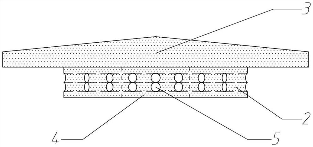
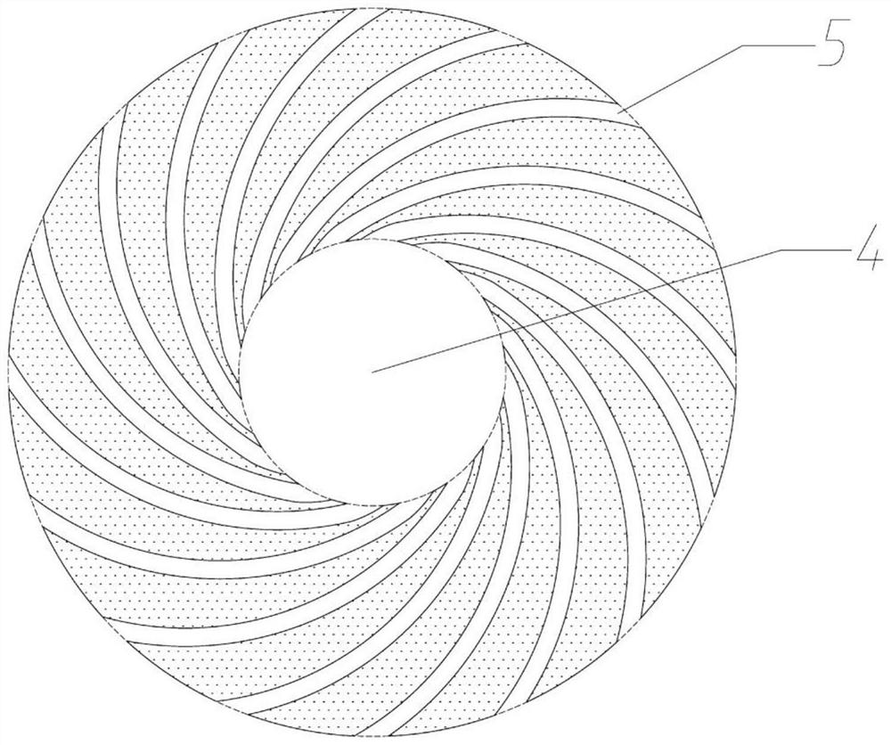
[0029] see Figure 1-5 , The present invention provides a technical scheme: the central sewage enhancer at the bottom of the high-level pool. The central sewage enhancer (1) at the bottom of the high-level tank includes: a base (2) and a cap (3), which are loaded into the sewage system of the original high-level tank. Figure 5 shown. There is a small hollow flat cylinder (4) in the middle of the base (2), the bottom of which is con...


PUM


Abstract

The invention discloses a central sewage discharge intensifier at the bottom of a higher-place pond. The central sewage discharge intensifier comprises a base and a cap, the base is a flat cylinder, 24-36 arc-shaped flow guide pipes are horizontally distributed on two layers of the flat cylinder, the arc-shaped flow guide pipes are evenly arranged anticlockwise, the top of the cap is conical and covers the base, and the diameter of the cap is larger than or equal to 50% of the diameter of the base. The impeller type oxygen adding machine of the higher-place pond rotates a water body anticlockwise, flowing dirt such as residual feed and excrement deposited at the bottom of the pond is collected to the middle area of the bottom of the pond, the central pollution discharge intensifier at the bottom of the higher-place pond is loaded at an inlet of an original pollution discharge system, and when the pollution discharge system is started, the dirt is transversely drained through the arc-shaped flow guide pipe according to the fluid mechanics principle; under the joint pressing of the flat base and the wide cap, a strong vortex is automatically generated in the center of the pond bottom, fluid dirt in the middle of the pond bottom is powerfully sucked and discharged, a good growth environment is created for fishes and shrimps, and the breeding goals of energy conservation, high yield, stable yield and environmental protection are achieved.

Description

technical field [0001] The invention relates to the technical field of aquaculture, in particular to a central sewage enhancer at the bottom of a high-level tank. Background technique [0002] In the past 10 years, with the advancement and promotion of aquaculture technology, a large number of high-level pond aquaculture industries with high-density intensive fish and shrimp culture have emerged in coastal areas such as Guangdong, Guangxi, Fujian, Jiangsu, and Hainan in my country. Intensive business model. [0003] However, the existing technologies related to sewage discharge in high-level pools simply configure a filter cover or sedimentation funnel and an escape hood at the central sewage outlet of the pool, and there is no lateral drainage and strengthening device with self-suction and discharge function. When the sewage system is activated, the bottom of the pool is The flow-like dirt in the center presents longitudinal or umbrella-like suction and discharge. [0004]...

Claims


Application Information

Patent Timeline
Patent Type & Authority Applications(China)
IPC IPC(8): A01K63/04
CPCA01K63/04Y02A40/81
Inventor 陈治良关雅文陈宝茹
Owner 陈治良
Why Eureka
Try Eureka