Heat net water purifier

A technology for purifiers and heating network water, applied in chemical instruments and methods, water/sewage treatment, water/sewage treatment equipment, etc., can solve the problems of low temperature of heating network pipes, affecting heating quality, and difficulty in cleaning, etc. Achieve scientific and reasonable structural design, ensure work efficiency, and ensure the effect of operating safety

Inactive Publication Date: 2017-11-14
黄诚
View PDF7 Cites 0 Cited by
  • Summary
  • Abstract
  • Description
  • Claims
  • Application Information

AI Technical Summary

Problems solved by technology

[0005] The purpose of the present invention is to provide a heat network purifier to solve the problem that the existing heat network water pipes are easily blocked due to water quality, aging or other factors during use, resulting in low temperature of the heat network pipes and cleaning the pipes Due to the need to stop and clean up the work, it is difficult to clean up, which seriously affects the quality of heating

Method used


Image

  • Heat net water purifier
  • Heat net water purifier
  • Heat net water purifier

Examples


specific Embodiment approach 1

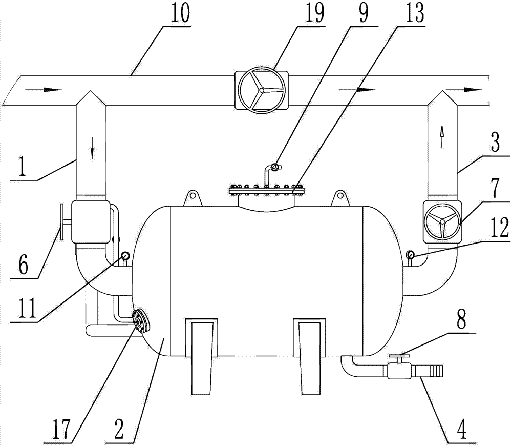
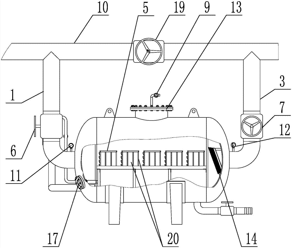
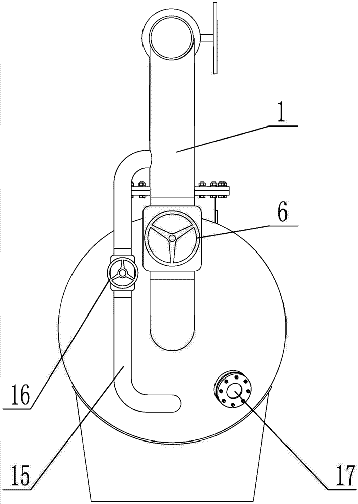
[0036] Specific implementation mode one: combine figure 1 , figure 2 , image 3 , Figure 4 , Figure 5 and Image 6 Describe this embodiment, this embodiment comprises water inlet pipe 1, tank body 2, outlet pipe 3, sewage pipe 4, water inlet valve 6, water outlet valve 7, sewage valve 8, air valve 9 and several magnetic rod groups 5, described The water inlet end of the water inlet pipe 1 is connected with the return pipe 10 of the secondary network of the heating network, the water outlet end of the water inlet pipe 1 is connected with one end of the tank body 2, and the other end of the tank body 2 is connected with the water inlet end of the water outlet pipe 3 The water outlet end of the outlet pipe 3 is connected with the return pipe 10 of the secondary network of the heating network, and the several magnetic bar groups 5 are arranged in the tank body 2, and the bottom of the tank body 2 is connected with a sewage pipe 4, and the tank body 2 The top of the body 2 ...

specific Embodiment approach 2

[0039] Specific implementation mode two: combination figure 1 and figure 2 To illustrate this embodiment, in this embodiment, the water inlet pipe 1 is provided with a water inlet pressure gauge 11 , and the water outlet pipe 3 is provided with a water outlet pressure gauge 12 . Other unmentioned structures and connections are the same as those in the first embodiment.

specific Embodiment approach 3

[0040] Specific implementation mode three: combination figure 1 , figure 2 and image 3 This embodiment is described. In this embodiment, a manhole door 13 is arranged on the top of the tank body 2 , and the air valve 9 is arranged on the manhole door 13 . Other unmentioned structures and connections are the same as those in the first or second embodiment.

[0041] Specific implementation mode four: combination figure 1 , figure 2 and image 3 To illustrate this embodiment, in this embodiment, the tank body 2 is provided with a large-aperture blocking net 14, and the large-aperture blocking net 14 is detachably connected to the water inlet end of the water outlet pipe 3, and each magnetic rod group 5 is close to the water outlet. One end of the water pipe 3 and both sides of the magnetic rod group 5 are respectively provided with a small-diameter blocking net 20 .

[0042] In this embodiment, both the large-aperture blocking net 14 and the small-aperture blocking net 2...


PUM


Abstract

The invention discloses a heat net water purifier and relates to a purifier used in a heat net water pipe. An existing heat net water pipe has the defects that a pipeline is easily blocked in the use process due to water quality, aging or other factors, and further the temperature of the heat net pipeline is low; the pipeline can be cleaned only under the shutdown condition, so that the cleaning difficulty is great and the heating quality is seriously affected. The heat net water purifier is characterized in that the water inlet end of a water inlet pipe is communicated with a second-stage heat net water returning pipe; the water outlet end of the water inlet pipe is communicated with one end of a tank body; the other end of the tank body is communicated with the water inlet end of a water outlet pipe; the water outlet end of the water outlet pipe is communicated with the second-stage heat net water returning pipe; a magnetic stripe rack is arranged in the tank body; a blowdown pipe is communicated to the bottom of the tank body; an air valve is arranged at the top of the tank body; a water inlet valve is arranged on the water inlet pipe; a water outlet valve is arranged on the water outlet pipe; a blowdown valve is arranged on the blowdown pipe. The product is used for purifying work of a heat net pipeline.

Description

technical field [0001] The invention specifically relates to a heat network purifier. Background technique [0002] Residents in northern China have to spend a long winter, and the heating system is an important guarantee for residents to keep warm in the cold winter. The heating system has become a necessary demand for northern residents to rely on in winter. After a long period of development, the current heating system has gradually matured and can well guarantee the heating of residents. Central heating has become the main heating method. , The heating and heating system is generally a water heating method, through the flow of hot water in the heating pipes of the residents' homes, it stays for heating, but when the hot water is running in the pipeline, the radiators are often not hot or the water flow is not smooth Happening. Or the blockage of the pipeline in the heating secondary network system directly affects the quality of heating and heating. These problems in t...

Claims


Application Information

Patent Timeline
Patent Type & Authority Applications(China)
IPC IPC(8): C02F1/48
CPCC02F1/481C02F2201/48
Inventor 黄诚
Owner 黄诚
Why Eureka
Try Eureka