Remote iris tracking and acquiring method based on microphone array

A technology of microphone array and acquisition method, which is applied in speech analysis, instruments, character and pattern recognition, etc., can solve problems such as incompetence for high-accuracy tasks, and achieve fast verification speed, improved robustness, and strong practicability Effect

Active Publication Date: 2017-11-14
伊沃人工智能技术(江苏)有限公司
11 Cites 16 Cited by

AI-Extracted Technical Summary

Problems solved by technology

However, the accuracy of voiceprint recognition is still lower than that of fingerprints a...

Method used

The present invention organically combines sound source localization technology based on microphone array and far-field voice recognition and voiceprint recognition technology with the collection of iris image, and innovatively proposes to use the microphone array in the existing voice interaction equipment to Capture the location information of the speaker, and control the pan/tilt and zoom mo...

Abstract

The invention discloses a remote iris tracking and acquiring method based on a microphone array, which includes the following steps: S1, a sound source locating module of a microphone array is started according to the voice of a user distributed within the voice acquisition range of the distributed microphone array, and tracks and calculates the position information of the mouth of the user in a three-dimensional space in real time; S2, the sound source locating module transmits the position information to a central processing control module, and if the position information is within the work range of an infrared camera and a holder, the central processing control module makes a high-speed holder and zoom module of the infrared camera aligned with the head of the user for zoom-in focus shooting to get multiple infrared images of the head of the user; and S3, a voice wakeup module identifies whether the current user voice is an agreed wakeup word according to the voice; if the current user voice is not an agreed wakeup word, the voice is invalid, and the infrared images are ignored; and if the current user voice is an agreed wakeup word, the voice is valid, and the infrared images collected are used in iris recognition. The remote iris tracking and acquiring method of the invention has the advantages of high accuracy, high practicability and high verification speed.

Application Domain

Technology Topic

Acoustic source localizationWorking range +8

Image

  • Remote iris tracking and acquiring method based on microphone array
  • Remote iris tracking and acquiring method based on microphone array
  • Remote iris tracking and acquiring method based on microphone array

Examples

  • Experimental program(1)

Example Embodiment

[0017] The technical solutions in the embodiments of the present invention will be clearly and completely described below in conjunction with the accompanying drawings in the embodiments of the present invention. Obviously, the described embodiments are only a part of the embodiments of the present invention, rather than all the embodiments. Based on the embodiments of the present invention, all other embodiments obtained by those of ordinary skill in the art without creative work shall fall within the protection scope of the present invention.
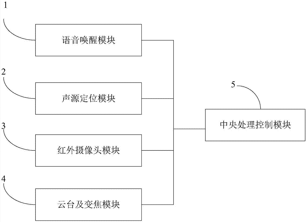
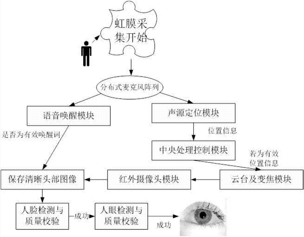
[0018] See Figure 1 to Figure 4 , A long-distance iris tracking and collection method based on a microphone array, including a central processing control module 5, a voice wake-up module 1 based on a distributed microphone array and a sound source positioning module 2 connected to it, and a remote iris collection method Image infrared camera module 3, pan/tilt and zoom module 4, including:
[0019] Step 1: The sound source positioning module of the microphone array is activated according to the user's voice distributed in the sound collection range of the distributed microphone array, and tracks and calculates the position information of the user's mouth in the three-dimensional space in real time;
[0020] Step 2: Transmit the position information to the central processing control module. If the position information is within the working range of the infrared camera and the pan/tilt, the central processing control module controls the high-speed pan/tilt and zoom module of the infrared camera to aim at the user Zoom in and focus on the head of the user to obtain multiple infrared images of the user’s head;
[0021] Step 3: The voice wake-up module recognizes whether the current user's voice is the agreed wake-up word according to the enhanced voice output by the microphone array. If not, it is an invalid voice and ignores the infrared image; if it is, it is a valid voice and will be collected The infrared image is used for iris recognition.
[0022] Preferably, when step 1, the distributed microphone array is composed of M (M> =1) Microphone arrays installed in different positions, assuming that the i-th microphone array contains N i Microphones, the entire distributed microphone array contains A microphone, the specific process of real-time tracking and calculating the position information of the user’s mouth in the three-dimensional space is:
[0023] Step 101: For the i-th by N i Microphone array composed of two microphones, N i ≥4, and cannot all be distributed on the same plane; microphones are paired in pairs to form n i =N i ×(N i -1)/2 pairs of microphones are paired; for each pairing, calculate the time difference τ of the voice of each pair of microphone channels ij , J=1,...,n i;
[0024] Step 102: According to the time difference of each pair of microphone channels, use Calculate α, where d ij Is the distance between the two microphones, and c is the speed of sound in the air, generally 340 m/s;
[0025] Step 103: Assume that the actual spatial positions of the two microphones in the j-th microphone pair are M respectively j1 (x j1 , Y j1 ,z j1 ) And M j2 (x j2 , Y j2 ,z j2 ), the included angle α and the included angle θ of the sound source relative to the array coordinate system in the three-dimensional space and The relationship is as follows:
[0026]
[0027]
[0028]
[0029] According to the pairwise pairing between multiple microphones, the corresponding sound source position information θ and When there are multiple distributed microphone arrays in the system, the θ obtained by each microphone array and The information is combined to obtain the position information of the user's mouth in the three-dimensional space.
[0030] Preferably, when performing step 2, the pan-tilt and zoom module take multiple pictures of human faces according to the position information output by the microphone array, wherein the size of the pictures of the human eyes meets the requirements of iris recognition, the specific steps are:
[0031] Step 201: According to the position information transmitted from the distributed microphone array sound source positioning module to the central control unit, judge whether the sound source coordinates are within the preset iris collection area, if yes, proceed to step 202; if not, it is an interference signal, ignore The location information.
[0032] Step 202: The central control unit controls the high-speed pan/tilt and zoom module of the infrared camera to aim at the sound source position in the space to take pictures;
[0033] Step 203: Perform face detection and eye detection on the collected head image, and extract iris images of both eyes for iris recognition; if the sharpness of the photo is lower than the preset value, because the image of human eyes cannot be accurately extracted, So ignore the image and continue processing the next one.
[0034] Preferably, when performing step 3, the specific steps are: step 301: the multi-channel voice collected by the microphone array undergoes echo cancellation, de-reverberation, beam integration, and post-filtering operations to obtain an enhanced single-channel voice. The voice recognition technology recognizes whether the current user's voice is an agreed wake-up word. If not, it is an invalid voice and ignores the infrared image; if it is, it is a valid voice, and the collected infrared image is used for subsequent iris recognition.
[0035] The speech recognition algorithm process in the wake-up module is that the speech audio is first processed by the speech front-end, and then the effective information is extracted through feature extraction, and then the audio is decoded. The decoding process includes the acoustic model, the pronunciation model and the language model, so as to convert the speech into Recognize the text, and then compare the wake words.
[0036] The present invention organically combines the sound source localization technology based on microphone array and far-field speech recognition and voiceprint recognition technology with the collection of iris image, and innovatively proposes to use the microphone array in the existing voice interaction device to capture the speaker The position information of the infrared camera is connected in parallel with the PTZ and zoom module of the infrared camera to dynamically collect clear images of the speaker’s head, making it possible to perform iris recognition and voiceprint recognition at the same time in remote scenes, and use the wake word recognition module to Judge whether the voice spoken by the user is an agreed-upon iris collection keyword, which reduces unnecessary false alarms and improves robustness.
[0037] The above descriptions are only preferred embodiments of the present invention and are not intended to limit the present invention. Any modification, equivalent replacement, improvement, etc. made within the spirit and principle of the present invention shall be included in the present invention. Within the scope of protection.

PUM

no PUM

Description & Claims & Application Information

We can also present the details of the Description, Claims and Application information to help users get a comprehensive understanding of the technical details of the patent, such as background art, summary of invention, brief description of drawings, description of embodiments, and other original content. On the other hand, users can also determine the specific scope of protection of the technology through the list of claims; as well as understand the changes in the life cycle of the technology with the presentation of the patent timeline. Login to view more.

Similar technology patents

Classification and recommendation of technical efficacy words

  • Practical
  • Improve accuracy

Optimization method for spray gun track of spraying robot on irregular polyhedron

ActiveCN102500498APracticalImprove work efficiency and product qualitySpraying apparatusSpecial data processing applicationsComputer Aided DesignParticle swarm algorithm
Owner:JIANGSU NEWBLUE INTELLIGENT EQUIP CO LTD

Cassette-based dialysis medical fluid therapy systems, apparatuses and methods

InactiveUS20050209563A1Improvement for dialysisImprove accuracyMedical devicesPeritoneal dialysisAccuracy improvementDialysis
Owner:BAXTER INT INC +1
Why Eureka
Try Eureka