Cantilever crane with reverse roller travelling trolley

A technology for running trolleys and cranes, applied in cranes, traveling mechanisms, transportation and packaging, etc., can solve the problems of inconvenience, waste of manpower and material resources, and the inability to directly hand over goods in the next workshop, achieving good grouping, cost saving, and easy coordination. Effect

Inactive Publication Date: 2017-11-17
卢统华
View PDF0 Cites 0 Cited by
  • Summary
  • Abstract
  • Description
  • Claims
  • Application Information

AI Technical Summary

Problems solved by technology

[0002] Existing bridge cranes are used in enterprise workshops. Some workshops are equipped with many machine tools for processing and production. Products and raw materials need to be transported to the next workshop or other departments in real time; the hooks of the cranes in the workshop are hung from the trolley. For hoisting goods, the trolley can only run back and forth along the double girders of the crane, and the crane can only run back and forth along the cart rails on the cross columns on both sides of the workshop, so that the range of goods that the crane hook can lift is within the distance between the two cart rails in the workshop. Within the plane surrounded by the two ends, when the goods at the edge of the plane need to be hoisted, the hook will be pulled obliquely, and the items farther away from this plane (such as outside the workshop door, outside the span) cannot be hoisted. At this time, it can only be transferred with the help of other transportation equipment. Usually, the car drives into the workshop to lift the goods under the hook. Go to the hook to hand over the goods, and some set up a special cantilever crane at the workshop door (or workshop aisle) to transfer and dispatch the goods outside the workshop, first hoist the goods into the place where the crane hook of the workshop can reach , and then the cargo is hoisted by the crane to other stations in the workshop. The existing bridge crane used in this working condition cannot directly transfer the cargo with the workshop next door, and must use other transportation equipment to schedule operations, which brings considerable inconvenience. It also wastes manpower and material resources

Method used


Image

  • Cantilever crane with reverse roller travelling trolley
  • Cantilever crane with reverse roller travelling trolley
  • Cantilever crane with reverse roller travelling trolley

Examples


Embodiment approach

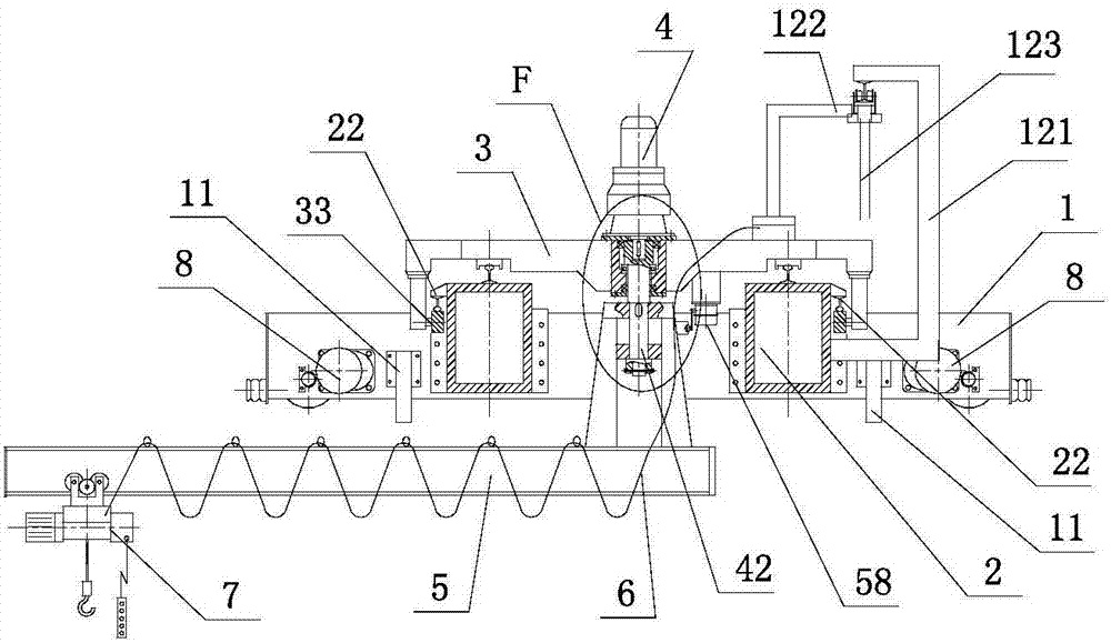
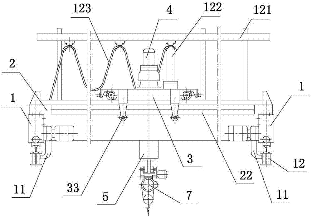
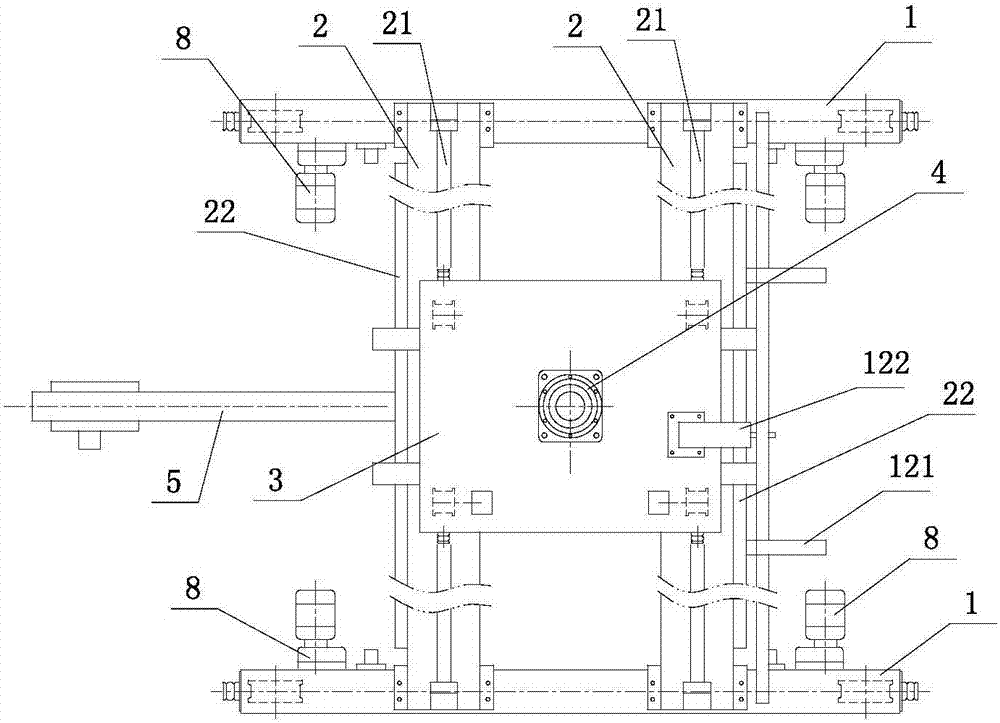
[0031] Such as figure 1 , figure 2 , image 3 As shown, a cantilever crane with a trolley running on reverse rollers includes two end girders 1 and two main girders 2, and the ends of the two main girders are respectively connected to the two end girders to form a bridge structure The outer side of one of the main girders is provided with a pick-up frame 121, and a hanging cable 123 is provided on the pick-up rack; a track 21 is arranged above the two main girders, and a running trolley 3 is connected on the track; The cables are connected to the hanging cables through the conductive frame 122; a steel rail 22 parallel to the above-mentioned rail 21 is arranged on the upper side of the two main girders, and the rail tread faces downward; Each piece is connected to two sets of anti-roller devices 33, and the anti-roller devices are lapped on the rail 22; the center of the running trolley is provided with a rotating mechanism 4; the boom shaft 42 in the rotating mechanism is ...


PUM


Abstract

This application discloses a cantilever crane with a trolley running on reverse rollers, which includes a bridge structure composed of two end girders and two main girders; There is a track, and the running trolley is connected to the track; a steel rail parallel to the above track and with the tread facing down is set above the outer side of the main beam; two sets of anti-rolling wheel devices are connected to each side of the running trolley through adjusting gaskets, and the anti-rolling wheel devices are connected to each other. Connected to the rail; there is a rotating mechanism in the center of the running trolley; the boom shaft in the rotating mechanism is connected to the cantilever component; a rotation limit device is set between the cantilever component and the running trolley; a set is installed at each end of the two end beams A cart driving device and a safety hook with shaft-connected wheels; an electric hoist is connected to the cantilever member, and the electric hoist can move back and forth horizontally along the cantilever beam; the cantilever beam is placed under the two main beams and can rotate.

Description

technical field [0001] The present application relates to the field of cranes, in particular to a cantilever crane with a trolley running on anti-rolling wheels. Background technique [0002] Existing bridge cranes are used in enterprise workshops. Some workshops are equipped with many machine tools for processing and production. Products and raw materials need to be transported to the next workshop or other departments in real time; the hooks of the cranes in the workshop are hung from the trolley. For hoisting goods, the trolley can only run back and forth along the double girders of the crane, and the crane can only run back and forth along the cart rails on the cross columns on both sides of the workshop, so that the range of goods that the crane hook can lift is within the distance between the two cart rails in the workshop. Within the plane surrounded by the two ends, when the goods at the edge of the plane need to be hoisted, the hook will be pulled obliquely, and the...

Claims


Application Information

Patent Timeline
Patent Type & Authority Applications(China)
IPC IPC(8): B66C23/88B66C6/00B66C9/14B66C9/08
CPCB66C23/88B66C6/00B66C9/08B66C9/14
Inventor 卢统华
Owner 卢统华
Why Eureka
Try Eureka