Swing dynamic load testing machine

A dynamic load testing machine and swing technology, which is used in the testing of mechanical parts, the testing of machine/structural parts, and measuring devices, etc., can solve the problems of simulated swing loss, casualties of small amusement facilities, and obstruction of product exports, and achieve the calculation results. reasonable effect

Pending Publication Date: 2017-11-17
QUALITY INSPECTING CENT OF PUMP & VALVE PROD OF ZHEJIANG PROVINCE +1
View PDF8 Cites 2 Cited by
  • Summary
  • Abstract
  • Description
  • Claims
  • Application Information

AI Technical Summary

Problems solved by technology

[0002] With the continuous improvement of people's living standards, the demand for small amusement facilities in children's entertainment places in kindergartens, schools, playgrounds and communities is also increasing, and the export volume of such amusement facilities is also increasing. The facilities and products are mixed, and there have been many accidents in which children used small amusement facilities to cause casualties. The quality standards of swings are not effectively in line with international standards. The influence of these technical barriers to trade produced by standard issues often causes product exports to be blocked. At present, the patent with the publication number

Method used


Image

  • Swing dynamic load testing machine
  • Swing dynamic load testing machine
  • Swing dynamic load testing machine

Examples


Embodiment Construction

[0019] The present invention will be described in further detail below in conjunction with the embodiments given in the accompanying drawings.

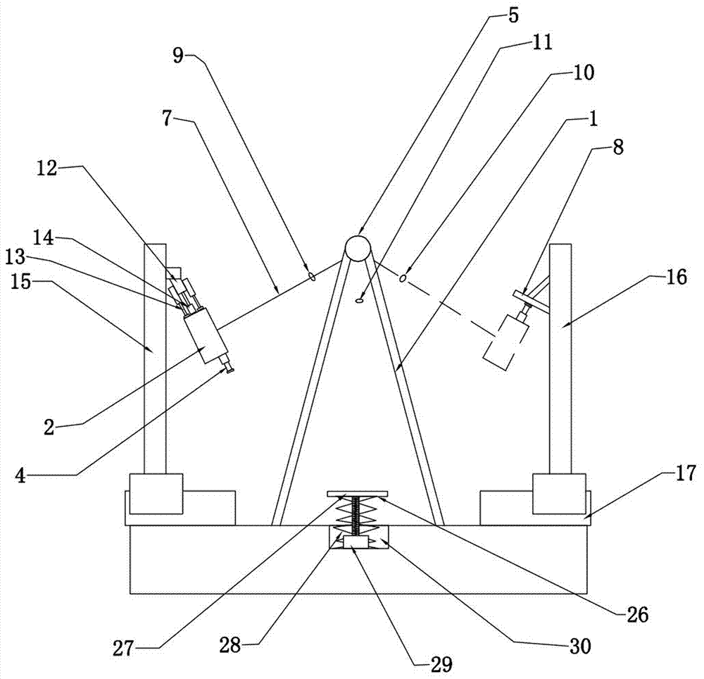
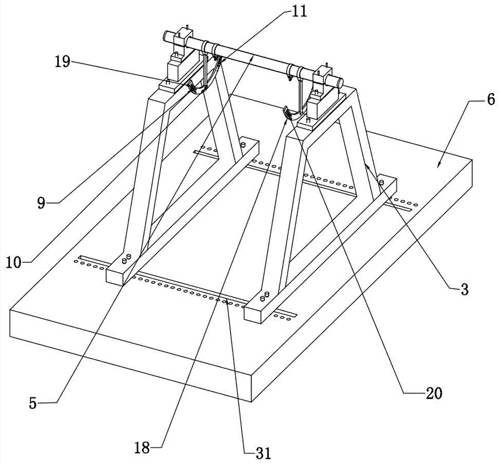
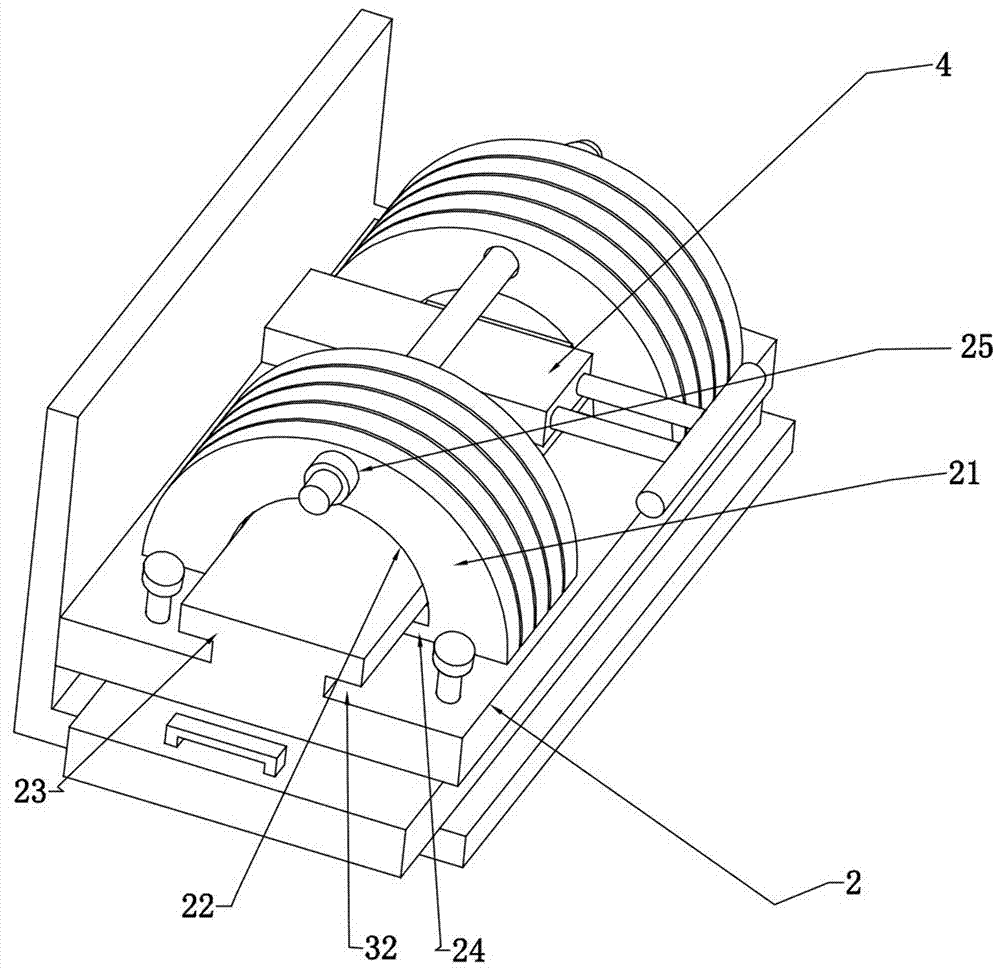
[0020] refer to Figure 1-3 As shown, a swing dynamic load testing machine disclosed in this embodiment includes a swing support 1, a load assembly 2 and a power unit, the power unit is a first cylinder 4 installed on the load assembly 2, and the upper end of the swing support 1 is equipped with A crossbeam 5, the crossbeam 5 is provided with a swing installation position, and a test piece 7 is hinged on the swing installation position, and the test piece 7 includes a swing arm and a seat plate, and the load assembly 2 is installed on the seat plate, preferably, its load Component 2 is clamped and installed on the seat plate by fasteners. The lower end of the test piece 7 is connected to the load component 2. The type of swing arm can be a rope, chain, fixed plate or other material connectors according to the type of swing. 2 include...


PUM


Abstract

The invention discloses a swinging dynamic load testing machine. The swinging dynamic load testing machine comprises a swing bracket, a load assembly and a first air cylinder which is mounted on the load assembly; the upper end of the swing bracket is provided with a cross beam; a test piece is hinged to the cross beam; the test piece comprises a swinging arm and a seat plate; the load assembly is mounted on the seat plate; one side of the swing bracket is provided with a baffle which can abut against the piston rod of the first air cylinder so that the piston rod of the first air cylinder can obtain a force; the swing bracket is provided with position sensors; the position sensors comprise a first sensor, a second sensor and a third sensor, wherein the first sensor and the second sensor are respectively arranged at two ends of the moving track of the test piece, and the third sensor is arranged between the first sensor and the second sensor; the mounting height of the first sensor is larger than the height of the second sensor; the first sensor is used for detecting the swinging amplitude of a swing; the second sensor is used for triggering the movement of the first air cylinder, so that the first air cylinder can apply a pushing force to the swing timely when the swinging amplitude of the swing is smaller than a certain range after energy is lost; and the third sensor is used for calculating the number of the times of the swinging of the test piece.

Description

technical field [0001] The invention relates to the field of dynamic load testing devices, in particular to a swing dynamic testing machine. Background technique [0002] With the continuous improvement of people's living standards, the demand for small amusement facilities in children's entertainment places in kindergartens, schools, playgrounds and communities is also increasing, and the export volume of such amusement facilities is also increasing. The facilities and products are mixed, and there have been many accidents in which children used small amusement facilities to cause casualties. The quality standards of swings are not effectively in line with international standards. The influence of these technical barriers to trade produced by standard issues often causes product exports to be blocked. At present, the patent with the publication number CN205103021 U discloses a swing fatigue testing machine, which includes two vertically arranged columns, cross bars and cros...

Claims


Application Information

Patent Timeline
IPC IPC(8): G01M13/00
CPCG01M13/00
Inventor 陈素娟金丽丽陈敬秒汤龙刚林快杨丽平
Owner QUALITY INSPECTING CENT OF PUMP & VALVE PROD OF ZHEJIANG PROVINCE
Why Eureka
Try Eureka