Magnetic adsorption charging mobile phone bracket

A technology of magnetic suction charging and mobile phone holder, which is applied in the direction of telephone structure, circuit, collector, etc., can solve the problems of unsafe driving, unsafe charging, large charging loss, etc., and achieve no radiation, low cost, and less charging loss Effect

Inactive Publication Date: 2017-11-17
北京看路科技有限公司
View PDF0 Cites 1 Cited by
  • Summary
  • Abstract
  • Description
  • Claims
  • Application Information

AI Technical Summary

Problems solved by technology

If you want to charge, you still have to plug the charging plug into the mobile phone to charge, which is inconvenient
And along with smart mobile phone develops faster and faster, function is more and more, and people are also more and more frequent to the use of mobile phone, but the battery capacity of mobile phone is but limited, and this just makes most smart mobile phone must charge for one to two days. , and most of the mobile phones are charged through the USB socket of the mobile phone, which creates a problem. Frequent plugging and unplugging will cause the charging socket to age, the metal elasticity will be reduced and damaged, and charging is not convenient
If you need to use the mobile phone while charging the mobile phone, you need to pull out the charging cable first. After use, you need to insert the mobile phone charging head when you put it back to charge. It is more inconvenient to use, and it is even more unsafe when driving. It is convenient. When you want to charge your phone halfway, you have to look away from the road to plug in the charging cable. It is very unsafe to pick up or charge your phone while driving. The cost of the magnetic induction module is also high, the charging loss is large, and there is radiation.

Method used


Image

  • Magnetic adsorption charging mobile phone bracket
  • Magnetic adsorption charging mobile phone bracket

Examples


Embodiment Construction

[0014] The following will clearly and completely describe the technical solutions in the embodiments of the present invention with reference to the accompanying drawings in the embodiments of the present invention. Obviously, the described embodiments are only some of the embodiments of the present invention, not all of them. Based on the embodiments of the present invention, all other embodiments obtained by persons of ordinary skill in the art without making creative efforts belong to the protection scope of the present invention.

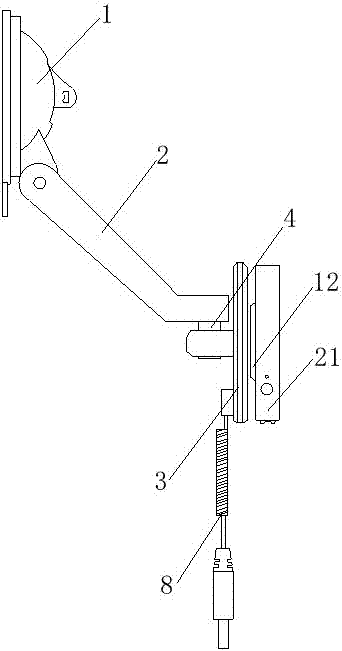
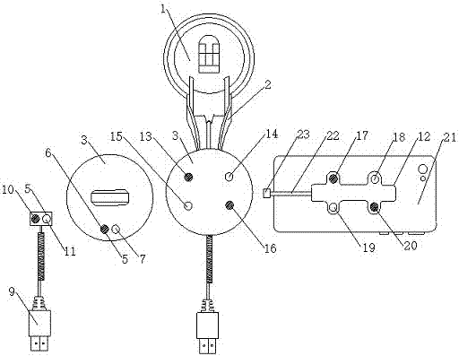
[0015] see Figure 1-2 , in an embodiment of the present invention, a mobile phone holder for magnetic suction charging, comprising a suction cup 1 and a magnetic charging disk 3, the suction cup 1 is connected to the bracket arm 2, the upper end of the bracket arm 2 is connected to the suction cup 1, and the lower end is connected to the magnetic charging disk 3, the bracket The lower end of the arm 2 is connected to the middle part of the back ...


PUM


Abstract

The invention discloses a magnetic charging mobile phone support, comprising a suction cup and a magnetic charging disk. The suction cup is connected to a support arm, the upper end of the support arm is connected to the suction cup, the lower end is connected to the magnetic charging disk, and the lower end of the support arm is connected to the magnetic charging disk. There is a limited rotating shaft, the lower back of the magnetic charging disk contains two magnet pieces, a magnetic charging cable is connected to the bottom of the back of the magnetic charging disk, one side of the magnetic charging cable is provided with a USB charging head, and the other The side contains two magnet pieces, the side of the magnetic charging cable containing the magnet pieces is connected to the magnetic charging disk, the front of the magnetic charging disk contains four magnet pieces, and the front of the magnetic charging disk is provided with a charging phone back sticker. The back of the charging mobile phone back sticker contains four magnet pieces, and the front side of the charging mobile phone back sticker is pasted with the mobile phone. This bracket does not need to be operated in sight, which is convenient, fast, low cost, less charging loss, no radiation and safer.

Description

technical field [0001] The invention relates to the technical field of mobile phone charging devices, in particular to a mobile phone holder for magnetic suction charging. Background technique [0002] Existing mobile phone holders only have the function of placing and fixing the mobile phone, but have no charging function. If you want to charge, you still need to insert the charging plug into the mobile phone to charge, which is inconvenient. And along with smart mobile phone develops faster and faster, function is more and more, and people are also more and more frequent to the use of mobile phone, but the battery capacity of mobile phone is but limited, and this just makes most smart mobile phone must charge for one to two days. , and most of the mobile phone charging is carried out through the USB socket of the mobile phone, which has just produced a problem, the frequent dialing and plugging will make the charging socket aging, the metal elasticity will be reduced and ...

Claims


Application Information

Patent Timeline
IPC IPC(8): H04M1/04H02J7/00H01R31/06H01R13/62
CPCH04M1/04H01R13/62H01R31/06H02J7/0045
Inventor 李新东王辉谌戈刁基煌
Owner 北京看路科技有限公司
Why Eureka
Try Eureka