Luggage case capable of improving antitheft capacity
A suitcase and ability technology, applied in the field of suitcases, can solve problems such as damage, anti-theft lock cracked or damaged, suitcase clothes or other items messed up, etc., to achieve the effect of firm suitcase, stable fit and improved anti-theft function
- Summary
- Abstract
- Description
- Claims
- Application Information
AI Technical Summary
Problems solved by technology
Method used
Image

Examples
Embodiment 1
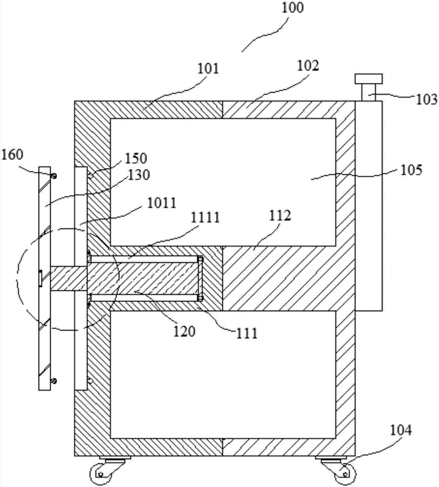
[0036] Such as figure 1 As shown, the present embodiment provides a luggage case with a lift table, the luggage case includes a case body 100, the case body 100 includes a case cover 101 and a case seat 102 that cooperate with each other, and the case body 100 is provided with an accommodating cavity 105; A first support column 111 and a second support column 112 are arranged in the cavity 105, one end of the first support column 111 and one end of the second support column 112 are against each other, and the other end of the first support column 111 and the second support column 112 The other end of the box cover 101 and the inner side wall of the box seat 102 are respectively connected.
[0037] The suitcase is a hard-shell suitcase. Through the corresponding arrangement of the first support column 111 and the second support column 112, the cooperation between the case cover 101 and the case seat 102 is more stable, making the suitcase stronger.
[0038] Such as figure 1 ,...
Embodiment 2
[0055] Such as Figure 6 As shown, the embodiment provides a luggage case that can prevent the clothes from shaking. The luggage case includes a case body 100, the case body 100 includes a case cover 101 and a case seat 102 that cooperate with each other, and the case body 100 is provided with an accommodating chamber 105; A first support column 111 and a second support column 112 are arranged in the cavity 105, one end of the first support column 111 and one end of the second support column 112 are against each other, and the other end of the first support column 111 and the second support column 112 The other end of the box cover 101 and the inner side wall of the box seat 102 are respectively connected.
[0056] The suitcase is a hard-shell suitcase. Through the corresponding arrangement of the first support column 111 and the second support column 112, the cooperation between the case cover 101 and the case seat 102 is more stable, making the suitcase stronger.
[0057] S...
Embodiment 3
[0071] Such as Figure 8 As shown, the embodiment provides a luggage case that can improve the anti-theft capability. The luggage case includes a case body 100, the case body 100 includes a case cover 101 and a case seat 102 that cooperate with each other, and the case body 100 is provided with an accommodating chamber 105; A first support column 111 and a second support column 112 are arranged in the cavity 105, one end of the first support column 111 and one end of the second support column 112 are against each other, and the other end of the first support column 111 and the second support column 112 The other end of the box cover 101 and the inner side wall of the box seat 102 are respectively connected.
[0072] Such as Figure 8 , Figure 9 and Figure 10 As shown, the second support column 112 is provided with an accommodating cavity 310, and the opening of the accommodating cavity 310 is provided with a cavity cover 311, and two first contact irons 320 are arranged o...
PUM
| Property | Measurement | Unit |
|---|---|---|
| Elastic modulus | aaaaa | aaaaa |
Abstract
Description
Claims
Application Information
PatSnap Eureka turns technology decisions into work you can execute. Powered by our Innovation Knowledge Graph, it runs expert workflows across engineering, life sciences, materials and intellectual property. Get your review-ready output in minutes.


