
Patsnap Eureka
For R&D, Patsnap Eureka makes reading and utilizing patents & technical documents easy.
Patsnap Eureka AIR
Designed for self-driven R&D workflows. Generate viable solutions, solve complex R&D challenges, empower your innovation with AI.

Patsnap Eureka Materials
Designed for material experts only. Revolutionize your material R&D, from search, analyze, to developing new materials.

TechResearch
Generate reliable direction feasibility study reports for your R&D in just a few steps.

TechSeek
Discover and master advanced knowledge NOW. Basics, ideas, possibilities, all at once.

TechMind
As an expert in R&D Theories, TechMind can generates customized viable solutions instantly.

TechRisk
Analyze your overall solution with one click, know your potential R&D risks in advance.

TechMonitor
Get weekly tech updates, stay abreast of the latest tech innovations and key insights.
Self-ligating bracket for orthodontics
An orthodontic self-locking and bracket technology, which is used in brackets, medical science, arch wires, etc., can solve the problems of difficult insertion of rough and hard orthodontic arch wires, inconvenient locking and unlocking operations, etc., and achieve easy unlocking operations. , the effect of convenient use
- Summary
- Abstract
- Description
- Claims
- Application Information
AI Technical Summary
Problems solved by technology
Method used
Image

Examples
Embodiment 1
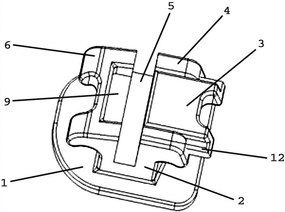
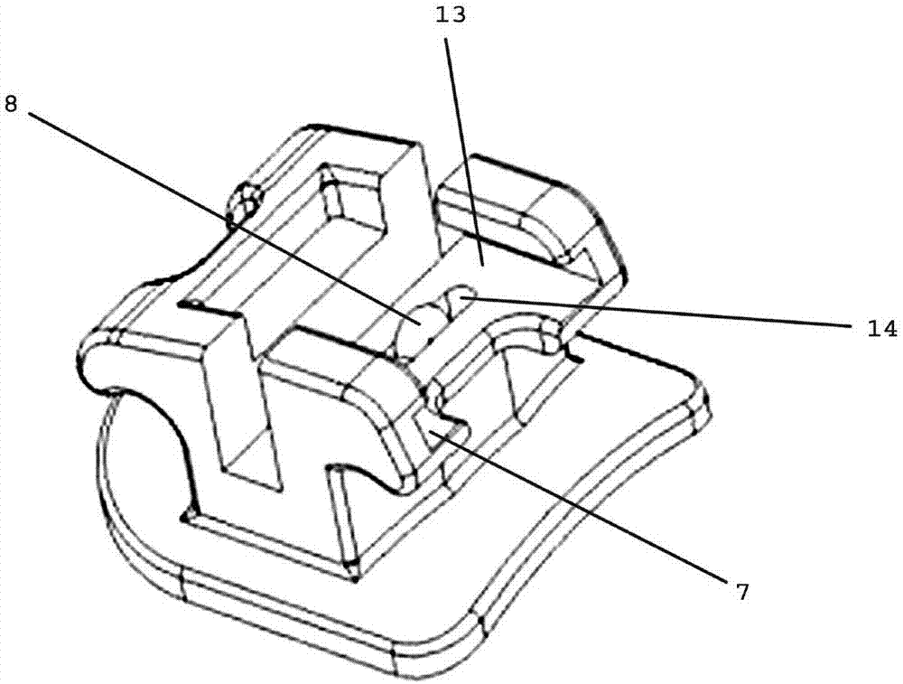
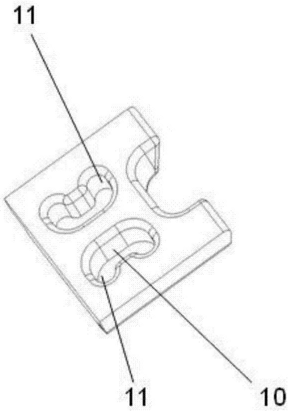
[0022] like figure 1 , figure 2 , image 3 , Image 6 As shown, the self-ligating bracket for orthodontics includes a bonded base plate 1, a bracket body 2, and a sliding cover 3. An archwire groove 5 is provided in the middle of the bracket body 2, and first ligating wings are respectively provided on both sides. 4. The second ligation wing 5, the first ligation wing 4 is provided with a dovetail chute 7, the two sides of the sliding cover 3 are provided with a dovetail convex groove 12, and the sliding cover 13 is arranged on the dovetail slide through the dovetail convex groove 12. Sliding fit with the first ligation wing 4 in the groove 7; a slide table 13 is provided below the dovetail chute 7, and the slide table 13 is provided with a long groove 14, and a U-shaped spring 8 is arranged in the long groove 14, and The U-shaped spring 8 is higher than the sliding table 13; the sliding cover 3 is provided with a locking groove 11 adapted to the U-shaped spring 8.
[002...
Embodiment 2
[0027] like figure 1 , Figure 4 , Figure 5 , Image 6 As shown, the self-ligating bracket for orthodontics includes a bonded base plate 1, a bracket body 2, and a sliding cover 3. An archwire groove 5 is provided in the middle of the bracket body 2, and first ligating wings are respectively provided on both sides. 4. The second ligation wing 5, the first ligation wing 4 is provided with a dovetail chute 7, the two sides of the sliding cover 3 are provided with a dovetail convex groove 12, and the sliding cover 13 is arranged on the dovetail slide through the dovetail convex groove 12. Sliding fit with the first ligation wing 4 in the groove 7; a slide table 13 is provided below the dovetail chute 7, and the slide table 13 is provided with a long groove 14, and a U-shaped spring 8 is arranged in the long groove 14, and The U-shaped spring 8 is higher than the sliding table 13; the sliding cover 3 is provided with a locking groove 11 adapted to the U-shaped spring 8.
[00...
PUM
 Abstract
Description
Claims
Application Information
 - R&D Engineer
- R&D Manager
- IP Professional
- Industry Leading Data Capabilities
- Powerful AI technology
- Patent DNA Extraction
Browse by: Latest US Patents, China's latest patents, Technical Efficacy Thesaurus, Application Domain, Technology Topic, Popular Technical Reports.
© 2024 PatSnap. All rights reserved.Legal|Privacy policy|Modern Slavery Act Transparency Statement|Sitemap|About US| Contact US: help@patsnap.com