Spring type electric rail clamping device

A rail clamp, spring-type technology, applied in the direction of travel mechanism, load hanging element, transportation and packaging, can solve the problem of affecting the clamping performance of the rail clamp, unable to achieve the clamping effect, etc., to improve the heat dissipation effect, Good clamping rail effect

Active Publication Date: 2017-11-21
芜湖火龙动力科技有限公司
View PDF6 Cites 5 Cited by
  • Summary
  • Abstract
  • Description
  • Claims
  • Application Information

AI Technical Summary

Problems solved by technology

[0002] The rail clamp is connected to the locomotive through the hole at the rear end of the clamp shaft. When the locomotive is running, when the drag (push) rail clamp moves synchronously, the guide wheel can roll along the serpentine track under the weight pressure of the rail clamp and pass through The guide wheel bracket and the pincer shaft drive the rail clamp to float on the fixed axis along the track surface. The automatic rail clamp can automatically lock the gantry crane on the track to prevent it from sliding when it is pushed by accident. However, the existing spring-type electric clamp Due to the large friction force generated during the clamping process of the rail clamp with the rail, a large amount of heat will be generated during the friction process, which will affect the clamping performance of the rail clamp to a certain extent, so it cannot be satisfied. The clamping effect, this defect causes the locomotive to still roll on the track for a relatively long distance during the working process of the clamp

Method used


Image

  • Spring type electric rail clamping device
  • Spring type electric rail clamping device
  • Spring type electric rail clamping device

Examples


Embodiment

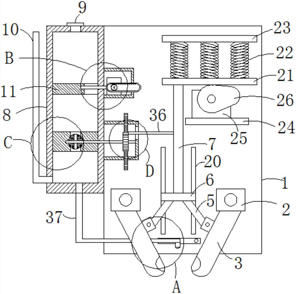
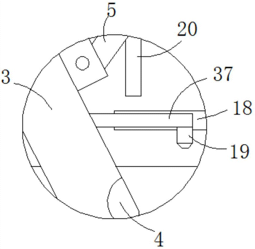
[0022] Such as Figure 1-5 As shown, a spring-type electric rail clamp includes a backboard 1, two fixed blocks 2 are fixedly connected to the side wall of the backboard 1, and the fixed block 2 is rotatably connected to a clamping plate 3, and the side of the clamping plate 3 The wall is provided with a clamping groove 4, specifically, the side walls of the clamping groove 4 are evenly distributed with protrusions, and the cross-section of the protrusions is triangular, which increases the roughness of the side walls of the clamping groove 4 and facilitates the clamping of the plate. 3 clamping track, the side wall of the clamping plate 3 is rotatably connected to the connecting rod 5, the upper end of the connecting rod 5 is fixedly connected to the middle plate 6, and the middle plate 6 is slidably connected to the side wall of the back plate 1, specifically, the back The side wall of the board 1 is provided with a chute 20, the side wall of the middle board 6 is fixedly co...


PUM


Abstract

The invention belongs to the technical field of hoisting equipment, and particularly relates to a spring type electric rail clamping device which comprises a back plate. Two fixing blocks are fixedly connected onto the side walls of the back plate and are rotationally connected with clamping plates, clamping grooves are formed in the side walls of the clamping plates, connecting rods are rotationally connected onto the side walls of the clamping plates, a middle plate is fixedly connected with the upper ends of the connecting rods and is slidably connected onto the side walls of the back plate, a movable rod is fixedly connected to the upper surface of the middle plate, and a movable mechanism is arranged on the upper side of the movable rod; a storage box filled with cooling liquid is fixedly connected onto a side wall of the back plate, a water-stop plug is plugged on a top plate of the storage box, and a liquid level pipe is fixedly connected onto a side wall of the storage box. The spring type electric rail clamping device has the advantages that excellent heat dissipation effects can be effectively realized when rails are clamped by the clamping plates, accordingly, the rails can be advantageously clamped by the clamping plates, and the spring type electric rail clamping device is worthy of being popularized.

Description

technical field [0001] The invention belongs to the technical field of hoisting equipment, in particular to a spring-type electric rail clamp. Background technique [0002] The rail clamp is connected to the locomotive through the hole at the rear end of the clamp shaft. When the locomotive is running, when the drag (push) rail clamp moves synchronously, the guide wheel can roll along the serpentine track under the weight pressure of the rail clamp and pass through The guide wheel bracket and the pincer shaft drive the rail clamp to float on the fixed axis along the track surface. The automatic rail clamp can automatically lock the gantry crane on the track to prevent it from sliding when it is pushed by accident. However, the existing spring-type electric clamp Due to the large friction force generated during the clamping process of the rail clamp with the rail, a large amount of heat will be generated during the friction process, which will affect the clamping performance ...

Claims


Application Information

Patent Timeline
Patent Type & Authority Applications(China)
IPC IPC(8): B66C9/18
CPCB66C9/18
Inventor 张益贵张益海姚彻友杭文才
Owner 芜湖火龙动力科技有限公司
Why Eureka
Try Eureka