Linkage table rotating base

A technology of rotating base and linkage table, applied in the field of linkage table, can solve the problems of unsatisfactory locking and unlocking method, inconvenience, fast wear speed, etc., and achieve the effect of good locking effect, simple and convenient operation, and long service life.

Active Publication Date: 2017-11-21
沈阳安控电气科技有限公司
View PDF6 Cites 7 Cited by
  • Summary
  • Abstract
  • Description
  • Claims
  • Application Information

AI Technical Summary

Problems solved by technology

[0003] There are many types of existing linkage table rotating bases, but the locking and unlocking methods are not ideal. Some are locked by rubber block friction. Locking by means of positioning pins, this method generally requires a large angle to set the positioning holes, which affects the conversion of the operator's viewing angle, and the wear speed is very fast; when the general linkage turntable is unlocked, the operator needs to operate by hand. In particular, it is very inconvenient to bend down; the common linkage turntable requires the operator to apply force to the ground through the feet to provide steering force when rotating, which brings inconvenience and increases operator fatigue;
[0004] In addition, it needs to be specially explained that the linkage table is installed on large-scale mechanical equipment such as cranes. At present, these large-scale mechanical equipment are accompanied by large vibrations during work. The working environment is very special and common in daily life. The various fixing and limiting methods are often difficult to play their due role in the environment of continuous vibration, or will lose their due effect in a short period of time, so the current linkage units on the market, especially the linkage units The base does not meet the requirements of use

Method used


Image

  • Linkage table rotating base
  • Linkage table rotating base
  • Linkage table rotating base

Examples


Embodiment Construction

[0101] The present invention will be further described in detail through the drawings and examples below. Through these descriptions, the features and advantages of the present invention will become more apparent.

[0102] The word "exemplary" is used exclusively herein to mean "serving as an example, embodiment, or illustration." Any embodiment described herein as "exemplary" is not necessarily to be construed as superior or better than other embodiments. While various aspects of the embodiments are shown in drawings, the drawings are not necessarily drawn to scale unless specifically indicated.

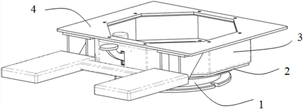
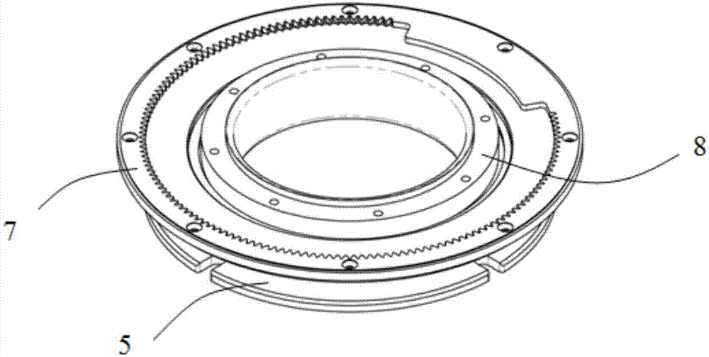
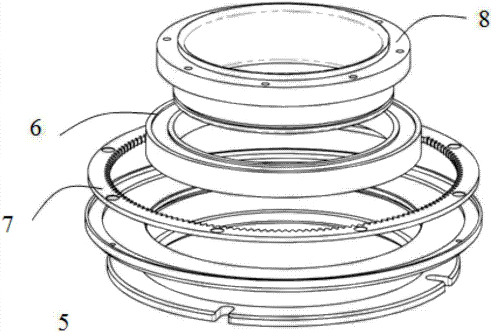
[0103] According to the present invention provides a rotating base of a linkage table, such as figure 1 , figure 2 , image 3 with Figure 5 As shown in , the rotating base of the linkage table includes a rotating assembly 1, a base 2, a box structure 3 and a bearing structure 4 installed sequentially from bottom to top,

[0104] The rotating assembly 1 includes a bearing sea...


PUM


Abstract

The invention discloses a linkage table rotating base. A unlocking panel is arranged in the rotating base, and is stepped to enable locking teeth of locking the rotating base to deviate from an inner gear ring; after the unlocking pedal is released, under the effect of a spring, the locking teeth and the inner gear ring are automatically engaged for locking the rotating base again, so that the rotating base cannot rotate; the rotating base is additionally provided with a driving mechanism comprising a motor, so that the rotation control of the rotating base can be realized through controlling a button; and in addition, the rotating base is provided with multiple limiting switches and limiting bolts for preventing wrong touch and overload to guarantee safe and stable system operation.

Description

technical field [0001] The invention relates to the control field of loading and unloading machinery, in particular to a linkage platform used for loading and unloading equipment such as cranes. Background technique [0002] The linkage table is a device used to control mechanical equipment such as cranes. During the control process, it is often necessary for the linkage table to be able to rotate so that the operator can change the viewing angle. [0003] There are many types of existing linkage table rotating bases, but the locking and unlocking methods are not ideal. Some are locked by rubber block friction. Locking by means of positioning pins, this method generally requires a large angle to set the positioning holes, which affects the conversion of the operator's viewing angle, and the wear speed is very fast; when the general linkage turntable is unlocked, the operator needs to operate by hand. In particular, it is very inconvenient to bend down; the common linkage tu...

Claims


Application Information

Patent Timeline
Patent Type & Authority Applications(China)
IPC IPC(8): B66C13/54B66C13/56
CPCB66C13/54B66C13/56
Inventor 杨柳
Owner 沈阳安控电气科技有限公司
Why Eureka
Try Eureka