High-precision micro-jet test pipeline device

A test pipeline and micro-jet technology, which is applied in the direction of measuring device, aerodynamic test, machine/structural component test, etc., can solve the problems of difficult small flow precise control, small flow adjustment characteristics, serious air leakage, etc. , to achieve the effect of broad application prospects, high flow control and measurement accuracy

Pending Publication Date: 2017-11-21
中国航空工业集团公司哈尔滨空气动力研究所
View PDF7 Cites 6 Cited by
  • Summary
  • Abstract
  • Description
  • Claims
  • Application Information

AI Technical Summary

Problems solved by technology

The micro-jet control method has achieved remarkable results and has broad application prospects. However, the original micro-jet test pipeline device has the following problems: 1) The flow rate is measured by a simple sonic nozzle, and the flow measurement accuracy is poor; 2) The flow control adopts continuous high-pressure regulation Ball valves have poor adjustment characteristics for small flow rates, and it is difficult to achieve precise control of small flow rates; 3) The integrated design of the pipeline pressure stabilizing chamber and the model, the sealing contact surface is a curved surface, and the air leakage is serious

Method used


Image

  • High-precision micro-jet test pipeline device
  • High-precision micro-jet test pipeline device
  • High-precision micro-jet test pipeline device

Examples


Embodiment Construction

[0011] The following specific implementation examples are listed in conjunction with the accompanying drawings to further illustrate the technical solution of the present invention.

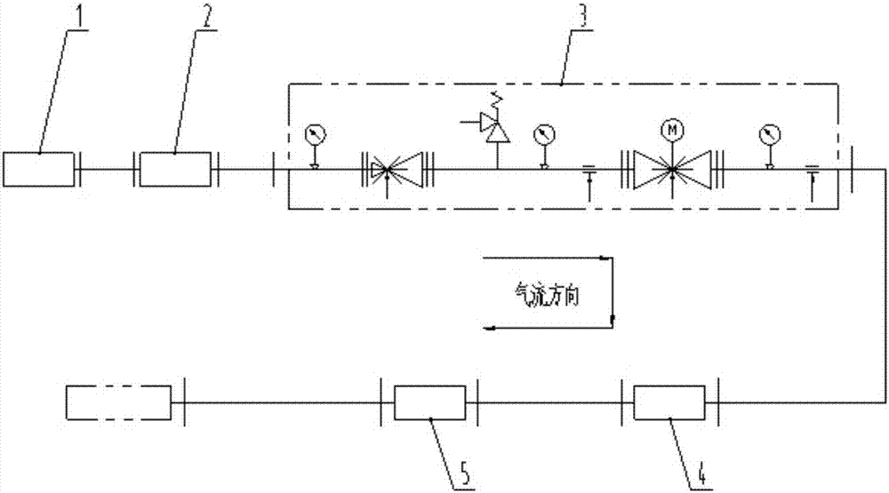
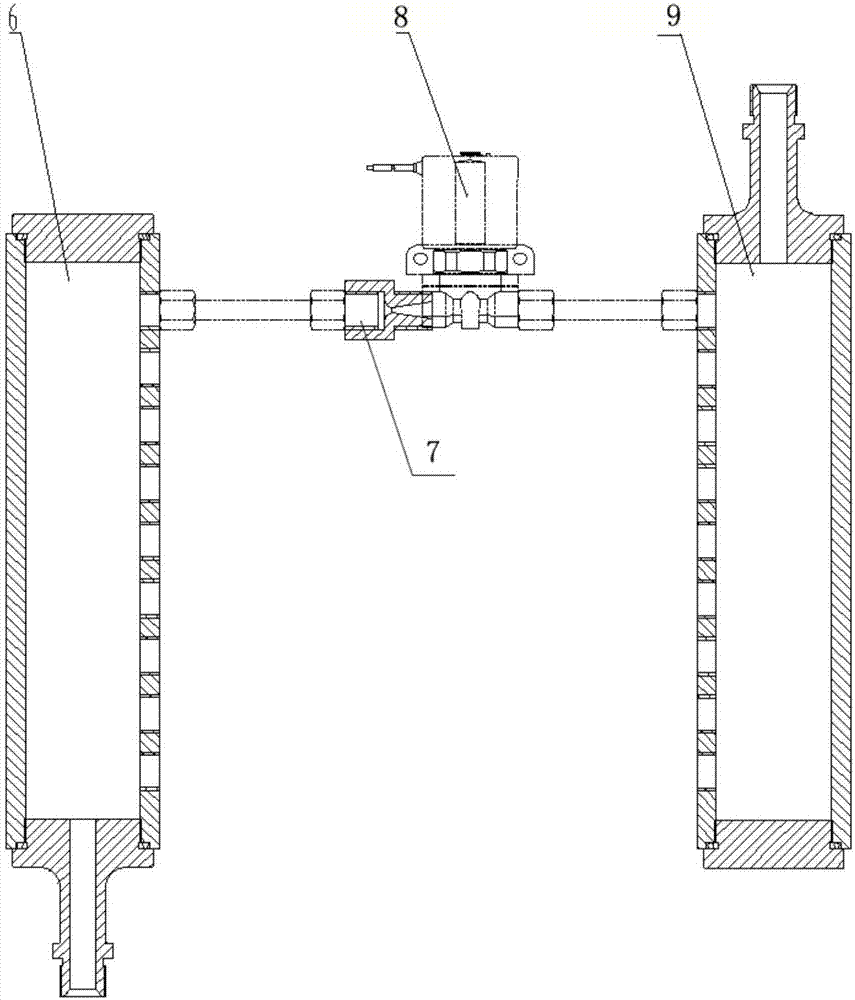
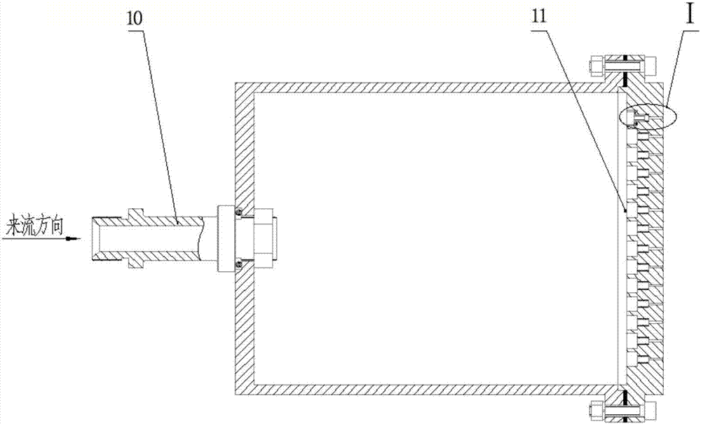
[0012] Such as Figure 1-4 As shown, a high-precision micro-fluidic test pipeline device includes a Coriolis flowmeter, a pressure-reducing regulator valve group, an 8-digit digital valve and a pressure-stabilizing chamber. The high-pressure gas is connected to the Coriolis flowmeter. The flowmeter is connected to the pressure-reducing and stabilizing valve group, the depressurizing and stabilizing valve group is connected to the 8-digit digital valve, the 8-digit digital valve is connected to the pressure-stabilizing chamber, and the pressure-stabilizing chamber is connected to the jet orifice of the test piece. The 8-digit The digital valve includes an air intake chamber, 8 Laval nozzles, 8 solenoid valves and an exhaust air collection chamber. There are 8 air outlet holes in the air inlet cham...


PUM


Abstract

The invention relates to a high-precision micro-jet test pipeline device. The high-precision micro-jet test pipeline device comprises a flowmeter, a pressure lowering and stabilizing valve group, a multi-position digital valve and a pressure stability cavity, wherein high-pressure gas is connected with the flowmeter, the flowmeter is connected with the pressure lowering and stabilizing valve group, the pressure lowering and stabilizing valve group is connected with the multi-position digital valve, the multi-position digital valve is connected with the pressure stabilizing cavity, the pressure stabilizing cavity is connected with a test piece jet hole plate, the multi-position digital valve comprises an air inlet and collecting chamber, a plurality of Laval nozzles, a plurality of electromagnetic valves and an air discharge and collecting chamber, the air inlet and collecting chamber is provided with a plurality of air outlets, one Laval nozzle is mounted at each air outlet, each Laval nozzle is connected with one electromagnetic valve, the air discharge and collecting chamber is provided with corresponding number of air inlets, and each electromagnetic valve is connected with the air inlet at the corresponding positon of the air discharge and collecting chamber. The high-precision micro-jet test pipeline device has the advantages that when the high-precision micro-jet test pipeline device is applied to an air inlet channel micro-jet flow controlled wind tunnel test, the device is stable in operation, jet flow is adjustable in a range of 0-0.032kg / s, and the device is high in flow control and measuring precision.

Description

technical field [0001] The invention specifically relates to a high-precision micro-jet test pipeline device. Background technique [0002] With the continuous development of aviation technology, many departments at home and abroad have carried out active and passive flow control research on the problem of ultra-compact S-shaped inlet flow separation. The control methods are different, but the general idea is to reduce the flow separation in the inlet. , Improve the total pressure recovery system, reduce flow distortion, etc. The control method involves vortex generator, vibrating spoiler, synthetic jet, micro jet and so on. The micro-jet control method has achieved remarkable results and has broad application prospects. However, the original micro-jet test pipeline device has the following problems: 1) The flow rate is measured by a simple sonic nozzle, and the flow measurement accuracy is poor; 2) The flow control adopts continuous high-pressure regulation Ball valves ha...

Claims


Application Information

Patent Timeline
Patent Type & Authority Applications(China)
IPC IPC(8): G01M9/02G01M9/06
CPCG01M9/02G01M9/06
Inventor 李长坤王文全杨威东魏立辉闫永昌高静
Owner 中国航空工业集团公司哈尔滨空气动力研究所
Why Eureka
Try Eureka