Optical element and reflection-type liquid crystal display system using same

An optical element and liquid crystal display technology, applied in optical elements, optics, nonlinear optics, etc., can solve the problems of limited light direction, loss of light energy, large reflection angle, etc., and achieve improved light utilization, good deflection effect, enhanced energy effect

Active Publication Date: 2017-11-21
BOE TECH GRP CO LTD
View PDF11 Cites 3 Cited by
  • Summary
  • Abstract
  • Description
  • Claims
  • Application Information

AI Technical Summary

Problems solved by technology

[0002] In the traditional reflective liquid crystal display system, the side-light light guide plate is used as the front light source system, and most of the outgoing light is light in a large-angle direction. In this way, the light entering the liquid crystal glass is also light in a large-angle direction. Finally, the three-color light reflected back will not enter the color film of the corresponding color because of the relatively large reflection angle, so a lot of light energy will be lost
[0003] There are also some reflective liquid crystal display systems that add multi-layer specially designed scattering films to reduce the large-angle outgoing light direction of the side-light light guide plate. Controlled light direction is limited, and the angle of change is not very ideal

Method used


Image

  • Optical element and reflection-type liquid crystal display system using same
  • Optical element and reflection-type liquid crystal display system using same
  • Optical element and reflection-type liquid crystal display system using same

Examples


Embodiment Construction

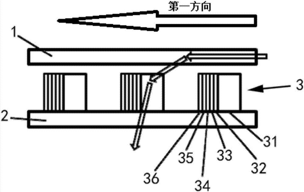
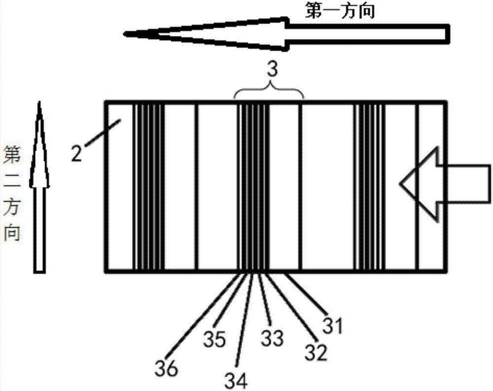
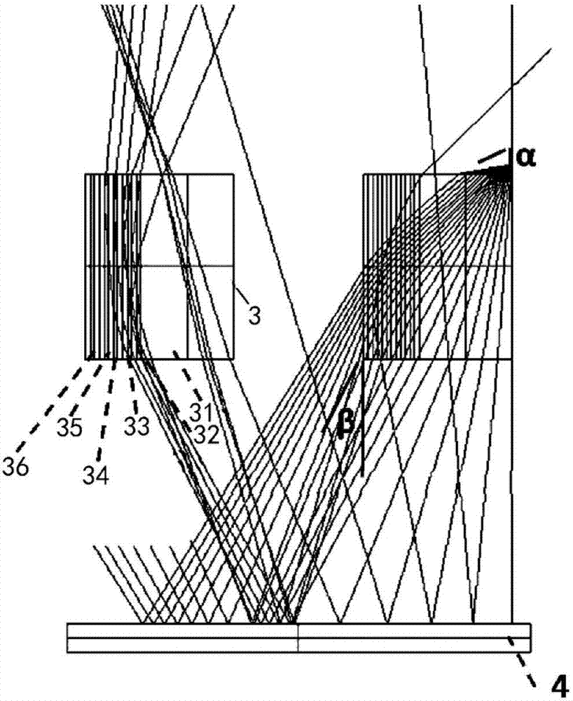
[0035] Example embodiments will now be described more fully with reference to the accompanying drawings. Example embodiments may, however, be embodied in many forms and should not be construed as limited to the examples set forth herein; the described features, structures, or characteristics may be combined in any suitable manner in one or more embodiments. In the following description, numerous specific details are provided in order to give a thorough understanding of embodiments of the present disclosure. However, those skilled in the art will appreciate that the technical solutions of the present disclosure may be practiced without one or more of the specific details being omitted, or other methods, components, devices, steps, etc. may be adopted.

[0036] It should be noted that in the drawings, the dimensions of layers and regions may be exaggerated for clarity of illustration. Also it will be understood that when an element or layer is referred to as being "on" another ...


PUM


Abstract

The invention provides an optical element, used in a reflection-type liquid crystal display system. The optical element comprises a base material, and a plurality of prisms which are formed on the base material and arranged along a first direction in sequence. Any one of the plurality of prisms is formed by a plurality of sub-prisms which are arranged along the first direction in sequence, refractive index of the plurality of sub-prisms decreasing in sequence. Through adding a prism array system formed by the plurality of prisms between a power supply and a reflection-type liquid crystal panel, each prism is formed by the plurality of sub-prisms, and the refractive index of the plurality of sub-prisms decreases from a near light end to a distance light end gradually, so that an angle of emergent light of a light source can be reduced, energy of available light entering the reflection-type liquid crystal display system is enhanced, and light utilization rate and screen brightness of a reflection-type liquid crystal display panel are improved.

Description

technical field [0001] The present disclosure relates to the display field, in particular, to an optical element and a reflective liquid crystal display system using the same. Background technique [0002] In the traditional reflective liquid crystal display system, the side-light light guide plate is used as the front light source system, and most of the outgoing light is light in a large-angle direction. In this way, the light entering the liquid crystal glass is also light in a large-angle direction. Finally, the three-color light reflected back will not be able to enter the color film of the corresponding color because of the relatively large reflection angle, so a lot of light energy will be lost. [0003] There are also some reflective liquid crystal display systems that add multi-layer specially designed scattering films to reduce the large-angle outgoing light direction of the side-light light guide plate. The direction of light to control is limited, and the angle ...

Claims


Application Information

Patent Timeline
Patent Type & Authority Applications(China)
IPC IPC(8): G02B5/04G02F1/1335
CPCG02B5/045G02F1/133606G02F1/133607G02F2201/30G02F1/133616G02F1/133553G02F1/133615
Inventor 杨泽洲祝明
Owner BOE TECH GRP CO LTD
Why Eureka
Try Eureka