Backlight module and display device

A backlight module and backlight technology, which is applied in the direction of light guides, optics, optical components, etc., can solve the problems of uneven brightness and darkness of the backlight module, increase the brightness and texture of the picture, save costs, and solve the problem of uneven brightness and darkness Effect

Inactive Publication Date: 2019-04-26
HUIZHOU CHINA STAR OPTOELECTRONICS TECHNOLOGY CO LTD
View PDF13 Cites 3 Cited by
  • Summary
  • Abstract
  • Description
  • Claims
  • Application Information

AI Technical Summary

Problems solved by technology

[0004] The object of the present invention is to provide a backlight module and a display device to solve the problem of uneven brightness and darkness of the backlight module in the prior art

Method used


Image

  • Backlight module and display device
  • Backlight module and display device
  • Backlight module and display device

Examples


Embodiment 1

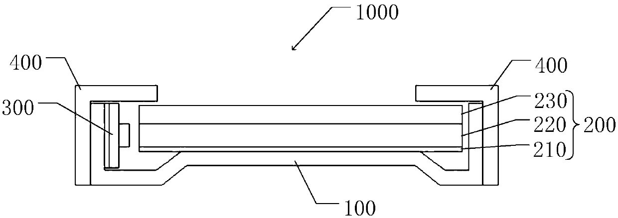
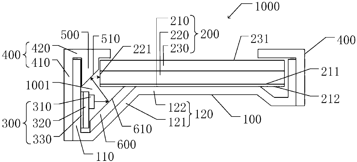
[0044] like image 3 As shown, a backlight module 1000 is provided in this embodiment, and the backlight module 1000 includes a backplane 100 , a film set 200 , a first reflector 500 , a second reflector 600 and a backlight 300 . The back plate 100 , the film set 200 and the first reflector 500 enclose a reflective chamber 1001 .

[0045] The backplane 100 is provided with a sideboard 110 and a bottom board 120 , and the sideboard 110 is vertically connected to the bottom board 120 . The bottom plate 120 includes a first board 121 and a second board 122 . The first plate 121 faces the first reflector 500 , and one end thereof is connected to the side plate 110 . One end of the second plate 122 is connected to the other end of the first plate 121 , and the other end is vertically connected to the other side plate 110 .

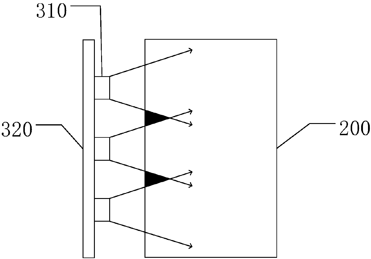
[0046] The diaphragm group 200 is disposed between the two side plates 110 , and has a light-incident side 221 and a light-outside 231 . The light-incident...

Embodiment 2

[0055] like Figure 4 As shown, a backlight module 1000 is provided in this embodiment, and the backlight module 1000 includes a backplane 100 , a film set 200 , a first reflector 500 , a second reflector 600 and a backlight 300 . The back plate 100 , the film set 200 and the first reflector 500 enclose a reflective chamber 1001 .

[0056] The backplane 100 is provided with a sideboard 110 and a bottom board 120 , and the sideboard 110 is vertically connected to the bottom board 120 . The bottom plate 120 includes a third board 123 , a fourth board 124 and a fifth board 125 . One end of the third board 123 is vertically connected to the side board 110 . The upper end of the fourth plate 124 is vertically connected to the other end of the third plate 123 . One end of the fifth plate 125 is vertically connected to the lower end of the fourth plate 124 , and the other end is vertically connected to the other side plate 110 .

[0057] The diaphragm group 200 is disposed betwee...

Embodiment 3

[0066] like Figure 5 As shown, a backlight module 1000 is provided in this embodiment, and the backlight module 1000 includes a backplane 100 , a film set 200 , a first reflector 500 , a second reflector 600 and a backlight 300 . The back plate 100 , the membrane group 200 and the first reflector 500 form a reflective chamber 1001 .

[0067]The backboard 100 is provided with a sideboard 110 and a bottom board 120 , and the two sideboards 110 are vertically connected to two sides of the bottom board 120 respectively. The backplane 100 in this embodiment can be stamped and formed by a sheet metal process. The bottom plate 120 has a sixth reflective surface 126, the sixth reflective surface 126 is the side of the bottom plate 120 facing the diaphragm group 200, and the sixth reflective surface 126 can have a reflective function during the manufacturing process of the back plate 100 through the sheet metal process . The sixth reflective surface 126 can also increase the reflec...


PUM


Abstract

The invention provides a backlight module. The backlight module comprises a backboard, a film piece set, a first reflection piece and a backlight source. The first reflection piece is provided with afirst reflection piece. The backboard, the film piece set and the first reflection piece enclose a reflection cavity, and the backlight source is placed in the reflection cavity. By additionally arranging the reflection piece and the reflection surface on the backlight module, the reflection cavity is formed, the light emitting direction and light emitting route of the backlight source are changed, therefore the route of light from the backlight source to the film piece set is prolonged so that the light can be subjected to coupling and reflection fully in the reflection cavity, and the wasteof the light source is reduced.

Description

technical field [0001] The invention relates to the field of display technology, in particular to a backlight module and a display device. Background technique [0002] In the liquid crystal display device, the liquid crystal display panel is a passive luminous element, which does not emit light itself, but is illuminated by the backlight module below it. The backlight module is a flat uniform lighting device, such as figure 1 As shown, it is generally equipped with a backlight source, a light guide plate, a reflector, a diaphragm module, a backplane and a middle frame. The backlight is generally EL (ElectroLuminescent, electroluminescent), CCFL (Cold Cathode Fluorescent Lamp, cold cathode fluorescent lamp) and LED (LightEmitting Diode, light-emitting diode). One has become the main backlight material on the market. CCFL is a line light source, and LED is a point light source. It is necessary to use a light guide plate to convert the line light source and point light sour...

Claims


Application Information

Patent Timeline
Patent Type & Authority Applications(China)
IPC IPC(8): G02F1/13357G02B6/00
CPCG02B6/0031G02F1/133615
Inventor 陈伟丰
Owner HUIZHOU CHINA STAR OPTOELECTRONICS TECHNOLOGY CO LTD
Why Eureka
Try Eureka