Coal-fired unit coupling biomass power generation system and method

A technology for biomass power generation and coal-fired units, which is applied in combustion methods, machines/engines, dryers, etc., can solve the problems of high investment cost, high failure, and large impact on the output of the pulverizing system, and achieves a simple and efficient system. , efficient coupling, the effect of reducing system investment

Pending Publication Date: 2021-07-23
XIAN THERMAL POWER RES INST CO LTD
View PDF0 Cites 6 Cited by
  • Summary
  • Abstract
  • Description
  • Claims
  • Application Information

AI Technical Summary

Problems solved by technology

Although the biomass molding and co-firing process adopted by a certain power plant can meet the needs of biomass co-firing, this process will increase the power consumption of the pulverization system due to the operation of a spare mill. In addition, the cost of biomass molding is high and the production Powder system output is greatly affected by biomass
According to the survey results of a foreign power plant, the co-grinding process was used to burn biomass in the first 5 years. Due to the large proportion of co-combustion and the difference in characteristics between biomass fuel and raw coal, the pulverized coal pulverization system has a certain degree of incompatibility. The failure is relatively high, and then it was transformed in 2011 to implement the independent combustion process, but the independent combustion process needs to add a complete set of crushing, conveying and combustion devices, and the overall investment cost is relatively high

Method used


Image

  • Coal-fired unit coupling biomass power generation system and method
  • Coal-fired unit coupling biomass power generation system and method

Examples


Embodiment Construction

[0028] Exemplary embodiments of the present disclosure will be described in more detail below with reference to the accompanying drawings. Although exemplary embodiments of the present disclosure are shown in the drawings, it should be understood that the present disclosure may be embodied in various forms and should not be limited by the embodiments set forth herein. Rather, these embodiments are provided for more thorough understanding of the present disclosure and to fully convey the scope of the present disclosure to those skilled in the art. It should be noted that, in the case of no conflict, the embodiments of the present invention and the features in the embodiments can be combined with each other. The present invention will be described in detail below with reference to the accompanying drawings and examples.

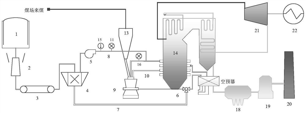
[0029] Such as figure 1 As shown, a coal-fired unit coupling biomass power generation system provided by the present invention includes a biomass field 1, a...


PUM


Abstract

The invention discloses a coal-fired unit coupling biomass power generation system and method. The coal-fired unit coupling biomass power generation system comprises a crushing mill, a conveyor, a hammer mill and a booster fan. An outlet of the crushing mill is connected to the input end of the conveyor, the output end of the conveyor is connected to a biomass powder inlet of the hammer mill, the hammer mill is further connected with a primary air bypass pipeline, and a biomass powder outlet of the hammer mill is connected to a primary powder pipe of the boiler through a biomass powder pipeline and the booster fan arranged on the biomass powder pipeline. The coal-fired unit coupling biomass power generation system and method are simple and efficient, large influences on the output of a unit coal mill in a co-grinding or forming blending combustion process is avoided, and the system investment of an independent spraying combustion process and the transformation influence on a boiler can also be reduced.

Description

technical field [0001] The invention belongs to the technical field of coal-fired coupled biomass power generation, and specifically relates to a coal-fired unit coupled biomass power generation system and method with low transformation cost and high adaptability to biomass. Background technique [0002] Biomass energy is a huge reserve, widely distributed, high-quality clean (CO 2 zero emission) renewable energy, the proper use of biomass will reduce CO 2 Emission reduction plays a huge role, among which biomass combustion power generation technology is an environmentally friendly, efficient and economical large-scale utilization technology, so it has received more and more attention from the energy field at home and abroad. At present, in the vast rural areas of our country, most of the biomass straws are directly burned and returned to the field, resulting in huge energy waste and environmental pollution. How to effectively use straw resources has become a common concern...

Claims


Application Information

Patent Timeline
Patent Type & Authority Applications(China)
IPC IPC(8): F23K1/00F23K3/02F23L15/00F23N3/00F23L1/00F23J15/02F26B17/10F26B21/00F01D15/10
CPCF01D15/10F23J15/022F23K1/00F23K3/02F23L1/00F23L15/00F23N3/00F26B17/10F26B21/001Y02E20/34
Inventor 王志超张喜来杨忠灿郭洋洲李宇航周广钦黄钢英司小飞姚伟
Owner XIAN THERMAL POWER RES INST CO LTD
Why Eureka
Try Eureka