Electronic product showing shelf

A technology for electronic products and display racks, which is applied to display hangers, display shelves, display stands, etc. It can solve the problems of fixed height of display boxes, high use limitations, and inability to adjust, so as to reduce use limitations and improve adaptability , the effect of improving reliability

Inactive Publication Date: 2017-11-24
YANCHENG SANDING ELECTRONICS TECH CO LTD
View PDF0 Cites 5 Cited by
  • Summary
  • Abstract
  • Description
  • Claims
  • Application Information

AI Technical Summary

Problems solved by technology

[0002] As we all know, an electronic product display stand is an auxiliary device used for displaying electronic products in the process of selling them so that customers can understand them more conveniently. It has been widely used in the field of electronic product display; existing The electronic product display stand includes a display box, a bracket and a bottom plate. The top of the bracket is connected to the bottom of the display box, and the bottom of the bracket is connected to the top of the bottom plate. There are four sets of first pick-and-place openings on the top, and the four sets of first pick-and-place openings are respectively connected with four sets of display chambers. Holes, and transparent baffles are set at the four groups of first observation holes; when using the existing electronic product display rack, just put the electronic product into any one of the four groups of display cavities for display In the use of the existing electronic product display racks, it was found that the height of the display box was fixed and could not be adjusted according to the display needs, resulting in poor adaptability; and the display box could not be rotated, resulting in high limitations in use; and it could not A detailed written introduction to an electronic product, resulting in its poor usability

Method used


Image

  • Electronic product showing shelf
  • Electronic product showing shelf
  • Electronic product showing shelf

Examples


Embodiment Construction

[0014] The specific implementation manners of the present invention will be further described in detail below in conjunction with the accompanying drawings and embodiments. The following examples are used to illustrate the present invention, but are not intended to limit the scope of the present invention.

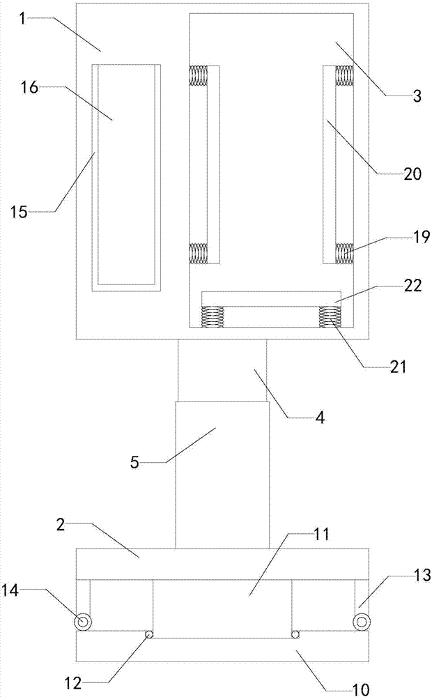
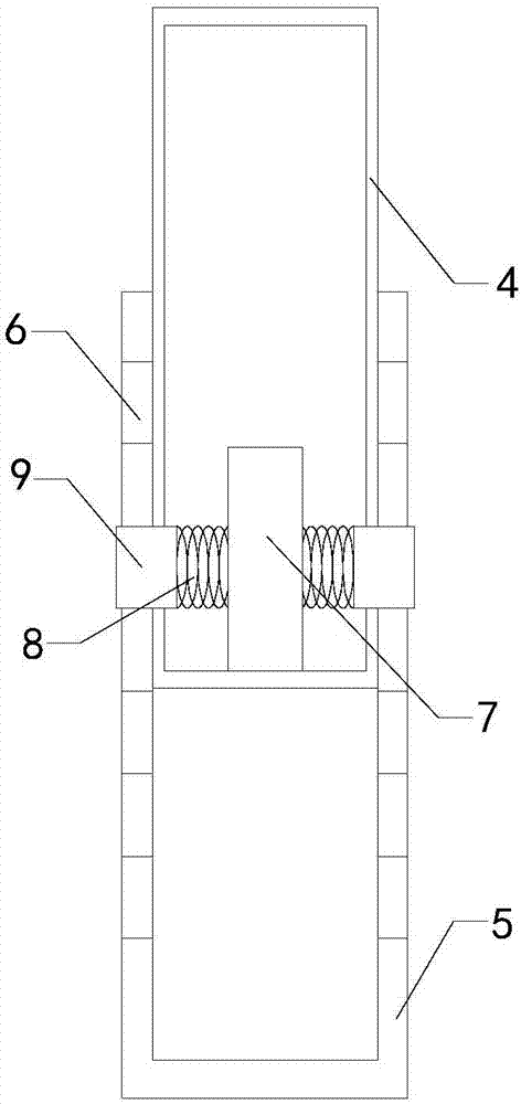
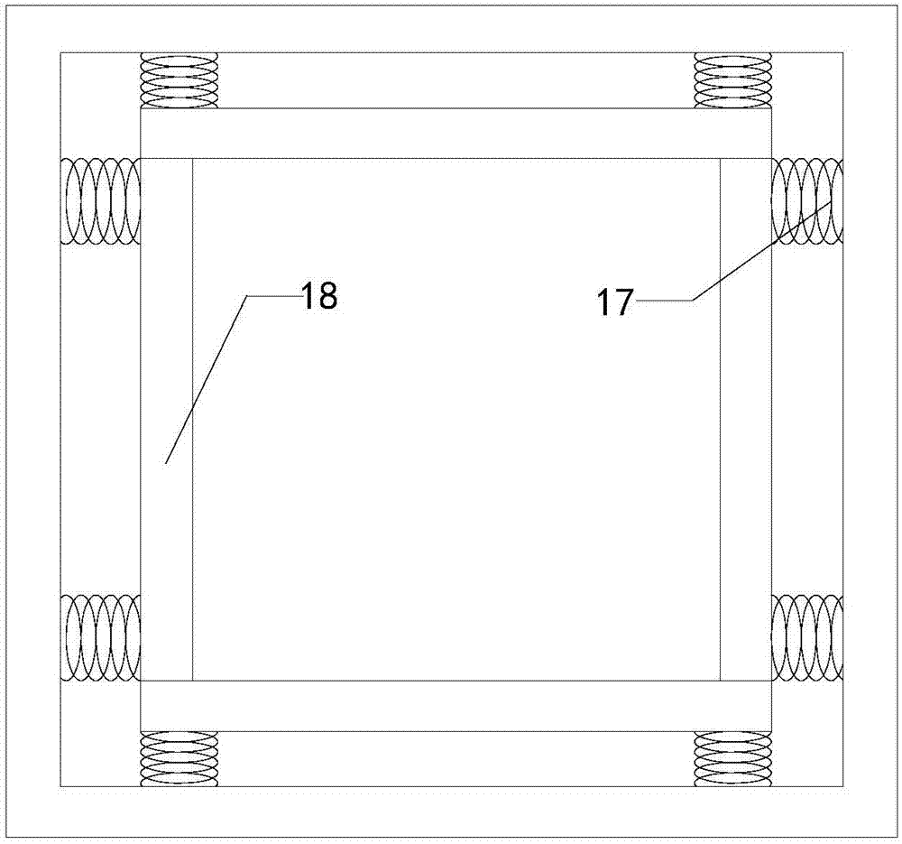
[0015] Such as Figure 1 to Figure 3 As shown, a display stand for electronic products of the present invention includes a display box 1, a bracket and a bottom plate 2, display cavities are arranged on the front side, rear side, left side and right side of the display box, and four groups are arranged on the top of the display box. The first pick-and-place openings, the four sets of first pick-and-place openings communicate with the four sets of display chambers respectively, and the front side wall, the rear side wall, the left side wall and the right side wall of the display box are all connected with the first observation hole, and in the four A first transparent baff...


PUM


Abstract

The present invention relates to the technical field of electronic product display attachments, in particular to an electronic product display rack, the height of which can be adjusted according to the display needs to improve its adaptability; and the display box can be rotated to reduce its use limitations ; and it can carry out detailed written introductions to electronic products, thereby improving its practicability; including display boxes, brackets and bottom plates, and the first transparent baffles are arranged at the four groups of first observation holes; , limit column, two sets of limit springs and two sets of limit blocks, a limit cavity is set in the insert column, and a plurality of left limit holes and a plurality of right limit holes are respectively arranged longitudinally on the left side wall and the right side wall of the intubation tube hole; also includes a support plate and a rotating column, the top of the support plate is provided with a placement groove, and a ball bearing is arranged in the placement groove; it also includes two sets of pillars and two sets of pulleys; it also includes four sets of business card boxes, and the second observation hole is provided with Second transparent baffle.

Description

technical field [0001] The invention relates to the technical field of electronic product display attachments, in particular to an electronic product display stand. Background technique [0002] As we all know, an electronic product display stand is an auxiliary device used for displaying electronic products in the process of selling them so that customers can understand them more conveniently. It has been widely used in the field of electronic product display; existing The electronic product display stand includes a display box, a bracket and a bottom plate. The top of the bracket is connected to the bottom of the display box, and the bottom of the bracket is connected to the top of the bottom plate. There are four sets of first pick-and-place openings on the top, and the four sets of first pick-and-place openings are respectively connected with four sets of display chambers. Holes, and transparent baffles are set at the four groups of first observation holes; when using t...

Claims


Application Information

Patent Timeline
Patent Type & Authority Applications(China)
IPC IPC(8): A47F7/00A47F3/11
CPCA47F7/00A47F3/004A47F3/005A47F3/11
Inventor 赵圣铭李彦龙
Owner YANCHENG SANDING ELECTRONICS TECH CO LTD
Why Eureka
Try Eureka