A roller feeding device for powder

A feeding device and rolling technology, applied in the field of powder rolling feeding device, can solve the problems of inconsistent distribution of silver powder, uneven feeding speed of silver powder, slag drop, etc., and achieve uniform feeding speed and reduce cost. The effect of spending and saving silver powder

Active Publication Date: 2019-03-26
CHINA ELECTRONIC TECH GRP CORP NO 18 RES INST
View PDF6 Cites 0 Cited by
  • Summary
  • Abstract
  • Description
  • Claims
  • Application Information

AI Technical Summary

Problems solved by technology

[0003] At present, the existing rolling feeding device often has the disadvantage of uneven feeding speed of silver powder, which leads to uneven distribution density of silver powder on the silver mesh, inconsistent silver powder adhesion strength and porosity of the positive electrode of the battery after rolling. Different problems; this problem will not only have a certain impact on the formation capacity, even after positive polarization, where the adhesion strength of silver powder is weak, slag and powder will appear after mechanical tests
[0004] In addition, the existing rolling feeding device cannot adjust the feeding amount, so it can only roll the positive electrode with a certain fixed thickness;
[0005] In addition, due to the existing rolling feeding device, there is no pre-leveling function for the silver expanded mesh before rolling, and the macroscopic unevenness of the silver expanded mesh will appear, resulting in inconsistent distribution of silver powder after rolling; at the same time, there is a lack of corresponding Length adjustment structure to roll the silver expanded mesh with different lengths;
[0006] Furthermore, powder leakage often occurs in the existing roller press feeding device, which increases the manufacturing cost

Method used


Image

  • A roller feeding device for powder
  • A roller feeding device for powder
  • A roller feeding device for powder

Examples


Embodiment 1

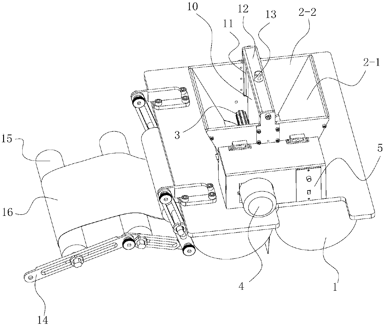
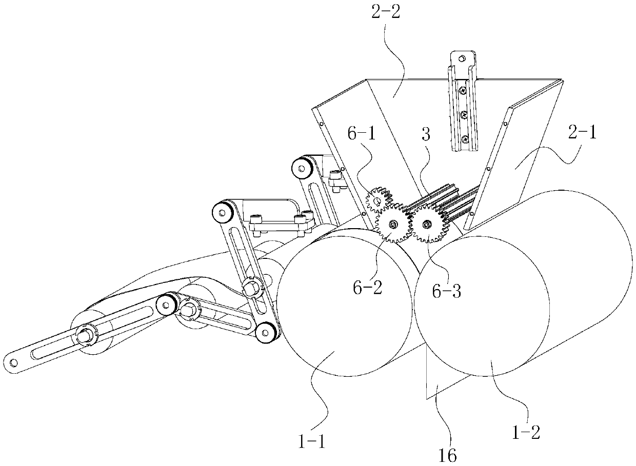
[0034] A rolling feeding device for powder, comprising a feeding hopper 2, the feeding hopper 2 is located directly above the two pressing rollers 1 of the rolling press; the two pressing rollers 1 are used for rolling on the rolling press The part of the silver stretch net 16 is driven to rotate by the roller press motor. These two pressing rollers 1 comprise the driving wheel pressing roller 1-1 of the side where the silver stretching net enters and the driven wheel pressing roller 1-2 that cooperates with the driving wheel pressing roller 1-1 to carry out rolling, and the driving wheel pressing roller 1-1 follows Clockwise rotation, driven wheel pressure roller 1-2 counterclockwise rotation. There is a certain gap between the driving wheel pressing roller 1-1 and the driven wheel pressing roller 1-2 according to the thickness of the silver expanded mesh 16 to be rolled. The position where the powder enters between the driving wheel pressing roller 1-1 and the driven wheel ...

Embodiment 2

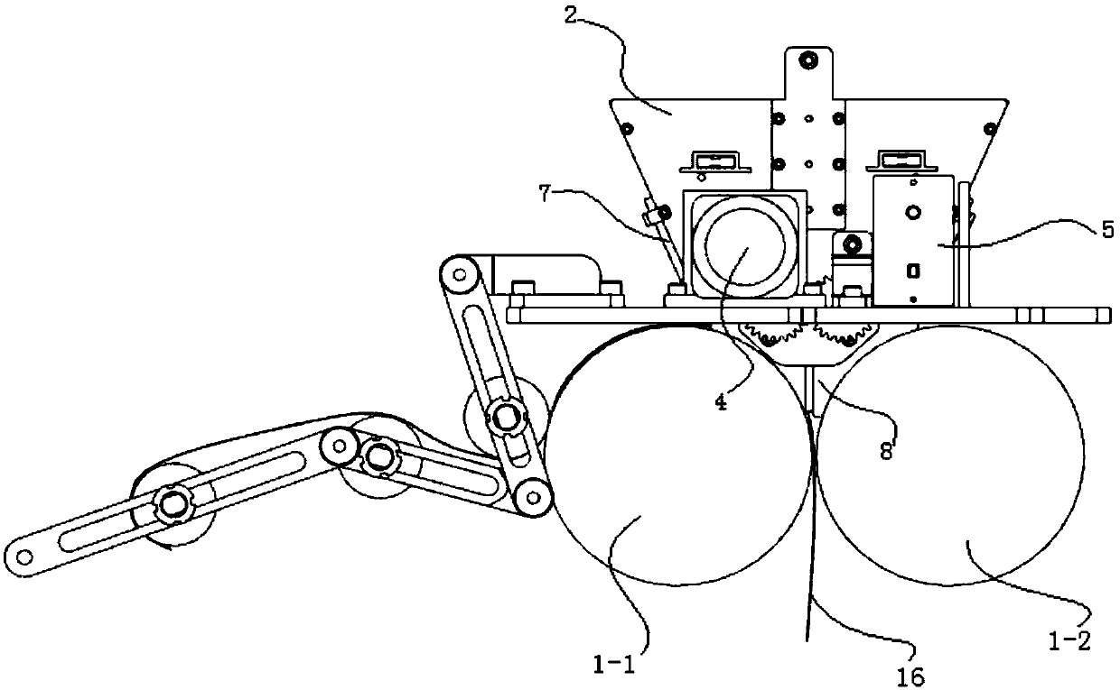
[0041] Since there is a gap between the bottom of the feed hopper 2 and the pressure roller 1, after the powder is filled, the powder will leak. Therefore, the difference between the second embodiment of the present invention and the first embodiment is that: On the basis, the automatic anti-leakage powder structure design is added, and it can adapt to the positive roll pressure under any roll spacing, saving silver powder and reducing costs.

[0042]The automatic anti-leakage powder structure includes two axial baffles 7 arranged along the roller axis and a radial baffle 8 perpendicular to the roller axis; the two axial baffles 7 are attached to the axial On the outer side of the baffle plate 2-1, the axial baffle plate 7 can slide downwards along the positioning fixtures arranged on the left and right sides of the axial baffle plate 2-1 until it fits with the silver net 16; The baffle plate 7 is a metal plate such as an iron plate or a steel plate. When placing the silver n...

Embodiment 3

[0045] In order to conveniently adjust the feeding amount of the powder, and roll out positive electrodes with different thicknesses, the third embodiment of the present invention is based on the first or second embodiment, adding the thickness of the positive electrode according to the thickness of the positive electrode in the feeding hopper 2. Feed adjustment mechanism to adjust the size of powder feed.

[0046] The feed adjustment mechanism is arranged above the roller nip, and the feed adjustment mechanism includes a slide rail 11 arranged inside two radial baffle plates 2-2 and an adjustment plate 10 that slides up and down along the slide rail 11 ; Preferably, the slide rail 11 uses polytetrafluoroethylene with self-lubricating effect. The thickness of the adjusting plate 10 is equal to or slightly larger than the gap between the driving wheel pressing roller 1-1 and the driven wheel pressing roller 1-2, so as the adjusting plate 10 moves up or down, the powder that can...


PUM


Abstract

The invention discloses a powder rolling feeding device, and belongs to the field of chemical power supplies. The powder rolling feeding device comprises a feed hopper; the feed hopper is positioned rightly above two pressure rollers of a rolling machine; a position for feeding powder between the two pressure rollers is a rolling port; the feed hopper is of a funnel structure for feeding the powder in the rolling port; the feed hopper consists of four baffle plates; impeller shafts parallel to pressure roller shafts are respectively arranged on the left and right sides of the rolling port; two ends of each impeller shaft are connected with two baffle plates perpendicular to the pressing roller shafts; two impeller shafts are connected with a rotary driving mechanism, and are driven by the rotary driving mechanism to oppositely rotate; each impeller shaft and the pressure roller in the same side are oppositely rotated; and the impeller shafts and the pressure rollers therebelow are provided with gaps at least capable of enabling silver pull nets to pass through. The powder rolling feeding device has such characteristics as uniform powder feeding speed, adjustable feeding quantity, capability of preleveling the silver pull nets, capability of adjusting the lengths of the silver pull nets and possession of an automatic powder leakage preventing function.

Description

technical field [0001] The invention belongs to the field of chemical power supply design, in particular to a powder rolling feeding device. Background technique [0002] Because of its excellent electrical and thermal conductivity and oxidation resistance, silver powder has become the material of choice for some battery positive electrode conductive fillers. The positive electrode of the aluminum-silver system battery is made of silver mesh as the skeleton, and the surface is filled with silver powder. After being rolled and formed, it is finally formed into a positive electrode. [0003] At present, the existing rolling feeding device often has the disadvantage of uneven feeding speed of silver powder, which leads to uneven distribution density of silver powder on the silver mesh, inconsistent silver powder adhesion strength and porosity of the positive electrode of the battery after rolling. Different problems; this problem will not only have a certain impact on the form...

Claims


Application Information

Patent Timeline
Patent Type & Authority Patents(China)
IPC IPC(8): B02C4/28B02C4/42B02C4/02
CPCB02C4/02B02C4/286B02C4/42
Inventor 牛长冬
Owner CHINA ELECTRONIC TECH GRP CORP NO 18 RES INST
Why Eureka
Try Eureka