Rapid coupling and positioning fixture for side vertical plates of bogie
What is Al technical title?
Al technical title is built by PatSnap Al team. It summarizes the technical point description of the patent document.
A positioning tooling and fast technology, applied in auxiliary devices, manufacturing tools, metal processing equipment, etc., can solve problems such as unfavorable classification inventory management, low positioning and unlocking efficiency, unfavorable production costs, etc., to achieve low cost, improve work efficiency and The effect of positioning accuracy and production cost saving
Active Publication Date: 2017-11-24
CRRC CHANGCHUN RAILWAY VEHICLES CO LTD
View PDF5 Cites 27 Cited by
Summary
Abstract
Description
Claims
Application Information
AI Technical Summary
This helps you quickly interpret patents by identifying the three key elements:
Problems solved by technology
Method used
Benefits of technology
Problems solved by technology
[0006] In order to solve the existing special operation process of first positioning the vertical vertical plate, multiple sets of horizontal or vertical clamps used in pairs, horizontal or vertical screw positioning tools and other auxiliary positioning tools are usually used in conjunction with the use, and the number of layouts is large, The positioning and unlocking efficiency is low, the operation is cumbersome, and it is not conducive to classified inventory management; and the vertical plate positioning method of prefabricated various slot tooling with different widths is poor in versatility, which is not conducive to saving production costs. The invention provides a bogie side Rapid assembly and positioning tooling for vertical panels
Method used
Image
Click on the blue label to locate the original text in one second.
Reading with bidirectional positioning of images and text.
Examples
Embodiment Construction
[0026] The present invention will be described in further detail below in conjunction with the accompanying drawings.
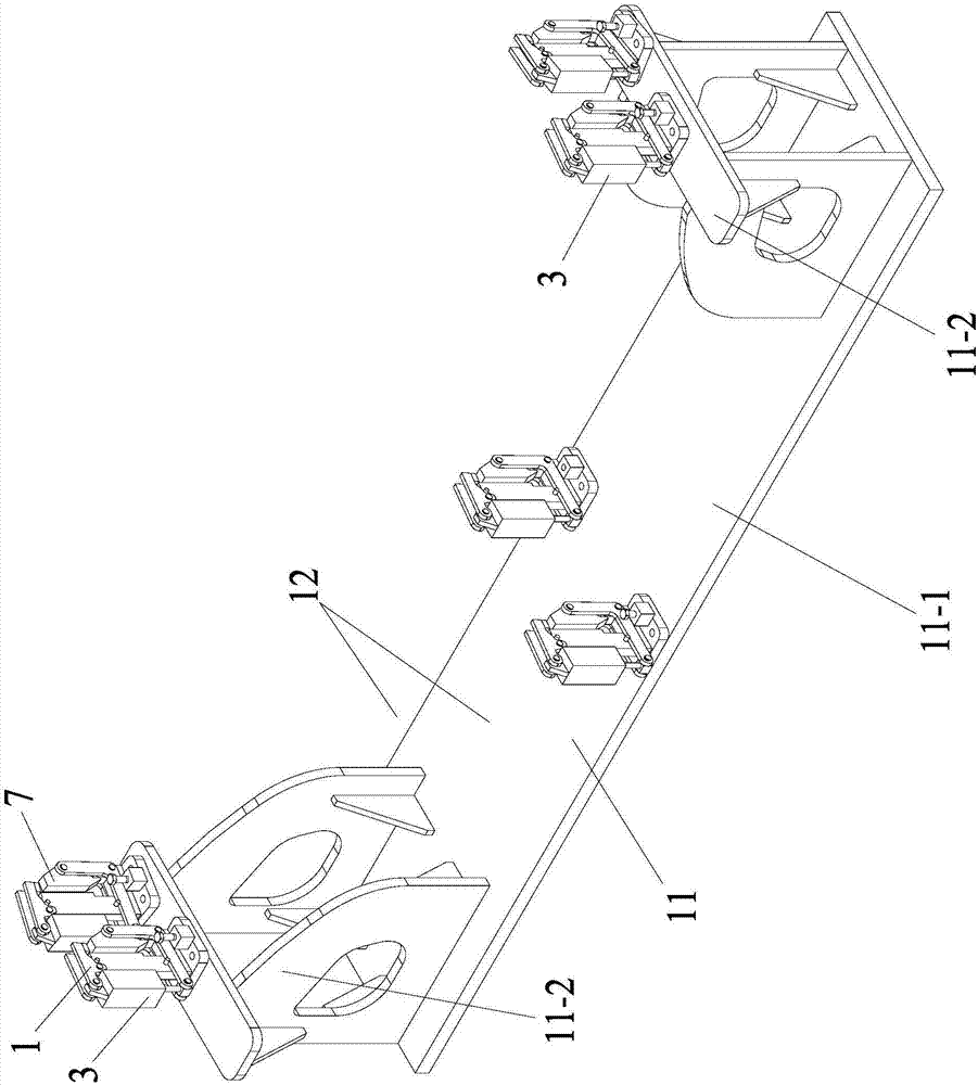
[0027] Such as Figure 3 to Figure 10 As shown, the bogie side vertical plate quick assembly and positioning tool of the present invention includes a pressing assembly 1, a component connecting shaft 2, a hydraulic device 3, an adjusting crankshaft 4, a stop pin 5, a base 6, a self-opening and closing adjustment block 7, Position the support frame, the limit pin 9, the support assembly 10 and the base 11. Among them, two pressing components 1, component connecting shaft 2, hydraulic device 3, adjusting crankshaft 4, stop pin 5, base 6, self-opening and closing adjustment block 7, positioning support frame, limit pin 9 and support component 10 are common A small-angle self-opening and closing clamping and positioning device is formed.
[0028] The base 6 is fixed on the base 11; the base 11 includes a low support 11-2 and two high support 11-2 at its two end...
PUM
Abstract
The invention discloses a rapid coupling and positioning fixture for side vertical plates of a bogie, belonging to the field of welding positioning assistant devices for the side vertical plates of the rail car bogie. The rapid coupling and positioning fixture comprises compression components, component connection shafts, hydraulic devices, adjustment crankshafts, banking pins, bases, self-opening-and-closing adjustment blocks, positioning support racks, limiting pins, support components and a substrate, wherein two compression components, one component connection shaft, one hydraulic device, two adjustment crankshafts, one banking pin, one base, one self-opening-and-closing adjustment block, one positioning support rack, one limiting pin and one support component jointly form one small-angle self-opening-and-closing clamping and positioning device. According to the rapid coupling and positioning fixture, by utilizing cooperative work of the multiple groups of small-angle self-opening-and-closing clamping and positioning devices, multiple side beam vertical plates can be precisely positioned synchronously, so that working efficiency and positioning precision of welding coupling operation are improved, and an inhibition effect of welding anti-deformation is realized.
Description
technical field [0001] The invention belongs to the field of welding and positioning auxiliary devices for side beam vertical plates of rail vehicle bogies, and in particular relates to a quick assembly and positioning tool for side vertical plates of a bogie. Background technique [0002] The frame and other mechanisms of rail cars use a large number of large parts with box-shaped cross-sections that are spliced and welded by multiple plates. Under many specific process design conditions, the production sequence of some of these parts is to place them vertically first. The vertical plate is then welded to the upper and lower end faces of the vertical plate or the bottom plate to finally form the required box-shaped large component structure. [0003] Such as figure 1 and figure 2 As shown, the side beam on the train frame is a box-shaped structure formed by joint welding of two bird-wing-shaped vertical plates 12 and other upper and lower cover plates. According to the...
Claims
Application Information
Patent Timeline
Application Date:The date an application was filed.
Publication Date:The date a patent or application was officially published.
First Publication Date:The earliest publication date of a patent with the same application number.
Issue Date:Publication date of the patent grant document.
PCT Entry Date:The Entry date of PCT National Phase.
Estimated Expiry Date:The statutory expiry date of a patent right according to the Patent Law, and it is the longest term of protection that the patent right can achieve without the termination of the patent right due to other reasons(Term extension factor has been taken into account ).
Invalid Date:Actual expiry date is based on effective date or publication date of legal transaction data of invalid patent.