Automobile with walking kinetic energy assisting in braking

A technology for auxiliary braking and automobiles, applied in the direction of brakes, braking components, vehicle parts, etc., can solve the problems of auxiliary braking and poor safety, achieve good anti-side impact ability, and increase the effect of elements participating in energy absorption

Inactive Publication Date: 2017-11-24
HANGZHOU GENCE TECH CO LTD
View PDF1 Cites 2 Cited by
  • Summary
  • Abstract
  • Description
  • Claims
  • Application Information

AI Technical Summary

Problems solved by technology

[0004] The first purpose of the present invention is to provide a walking kinetic energy auxiliary braking automobile that can use the kinetic energy of walking to perform auxiliary braking, which solves the problem that the existing automobiles cannot use the kinetic energy of walking to perform auxiliary braking
[0005] The second purpose of the present invention is to further provide a vehicle that can absorb side impact energy without the collapse and deformation of the vehicle frame when a side impact occurs, which solves the need for vehicle body collapse in the case of an existing vehicle side impact. The problem of poor safety caused by energy absorption

Method used


Image

  • Automobile with walking kinetic energy assisting in braking
  • Automobile with walking kinetic energy assisting in braking
  • Automobile with walking kinetic energy assisting in braking

Examples


Embodiment 1

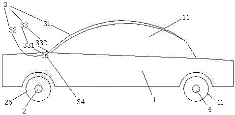
[0024] Embodiment one, see figure 1 , a vehicle with auxiliary braking by walking kinetic energy, comprising a vehicle body 1 and a wind braking mechanism 3 . The vehicle body 1 is provided with a roof 11 , a front axle 4 and a rear axle 2 . The front axle 4 is provided with front wheels 41 . The rear axle 2 is provided with rear wheels 26 . The wind braking mechanism 3 includes a wind deflector 31 , a support block 32 and a wind deflector driving mechanism 33 . The rear end of the windshield 31 is rotationally connected with the vehicle body 1 through a rotating shaft 34 . The windshield 31 is covered on the ceiling 11 . The support block 32 is located behind the rotating shaft 34 . The wind deflector driving mechanism 33 includes an electromagnet 331 and a ferromagnet 332 (that is, an object capable of being attracted by magnetic force). The electromagnet 331 is disposed on the support block 32 .

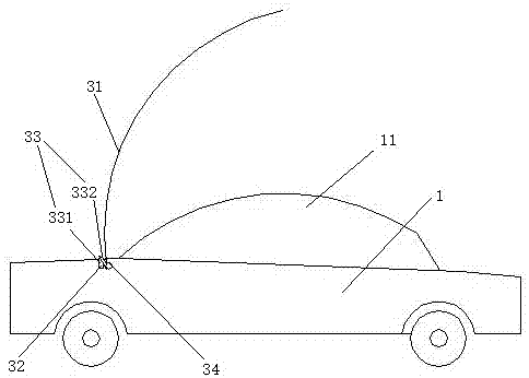
[0025] see figure 2 , when the vehicle brakes and needs auxiliary br...

Embodiment 2

[0026] Embodiment two, the difference with embodiment one is:

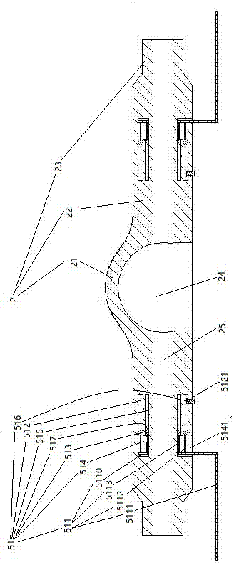
[0027] see image 3 , the rear axle 2 is provided with a reducer installation section 21 and two axle shaft installation sections 22 located on both sides of the reducer installation section. The free end of the axle shaft mounting section 22 is provided with a wheel joint 23 . The reducer installation section 21 is provided with a reducer installation cavity 24 . The half-shaft installation section 22 is provided with a half-shaft installation channel 25 extending from the end surface of the wheel joint 23 along the extension direction of the half-shaft installation section and communicating with the reducer installation cavity. A side impact energy-absorbing structure 51 is arranged inside the half-shaft installation section 22 .

[0028] The side impact energy-absorbing structure 51 includes a drive frame 511 , a cylinder 512 , a compression piston 513 , a first frictional energy-dissipating cylinder 514 and...

Embodiment 3

[0036] Embodiment three, the difference with embodiment two is:

[0037] see Figure 5 , the inner peripheral surface of the inner tube 5161 is provided with a vane 5168 that guides the sealing head 516 to rotate when the fluid flows through the inner tube. The half shaft installation section 22 is also provided with a support frame 518 . The supporting frame 518 is rotatably connected with a connecting sleeve 519 through a plane bearing 5181 . The connecting sleeve 519 is connected with an annular blade 5191 . A limiting portion 5192 is formed between the annular blade 5191 and the connecting sleeve 519 . The blade 5191 is provided with an annular cutting edge 5193 . The annular cutting edge 5193 is aligned with the bottom wall 5163 . The outer diameter of the blade 5191 is equal to the inner diameter of the inner circular tube 5161.

[0038] During use, if the sealing head 516 is ejected, before the annular cutting edge 5193 contacts the bottom wall 5163, the connectin...


PUM


Abstract

The present invention relates to automobiles. A kind of vehicle with auxiliary braking by walking kinetic energy, comprising a car body with a roof, a front axle, a wind braking mechanism and a rear axle, the front axle is provided with a front wheel, the rear axle is provided with a rear wheel, the wind force The brake mechanism includes a windshield covered on the ceiling, a support block, a windshield driving mechanism that drives the windshield to erect and abuts against the support block, and the rear end of the windshield passes through the rotating shaft to The car bodies are rotatably connected together, the support block is located behind the rotating shaft, and the windshield driving mechanism includes an electromagnet and a ferromagnet arranged on the windshield and matched with the electromagnet. The invention provides a walking kinetic energy auxiliary braking automobile which can use the kinetic energy during walking to perform auxiliary braking, and solves the problem that the existing automobiles cannot use the kinetic energy during walking to perform auxiliary braking.

Description

technical field [0001] The invention relates to automobiles, in particular to an automobile with walking kinetic energy auxiliary braking. Background technique [0002] A basic structure of a motor vehicle comprises a body with a roof, a front axle with front wheels, and a rear axle with rear wheels. The drive axle of a car consists of a final drive, a differential, a half shaft, and a rear axle. The final drive, differential, and drive axle components are installed in the rear axle, located at the rear of the car, and the power is transmitted to the rear wheels. Promptly disclose a kind of existing rear axle in the patent document of CN205853768U in Chinese patent publication. The basic structure of the existing rear axle includes a rear axle body. The rear axle body is provided with a reducer installation section and two half-shaft installation sections located on both sides of the reducer installation section. The free end of the half-shaft installation section is provi...

Claims


Application Information

Patent Timeline
IPC IPC(8): B60T1/16B60R19/42
CPCB60T1/16B60R19/023B60R19/42B60R2019/026
Inventor 危金兰
Owner HANGZHOU GENCE TECH CO LTD
Why Eureka
Try Eureka