Side-impact energy-absorbing type car crane span structure assmebly

A bridge and assembly technology, applied in the field of side impact energy-absorbing automobile bridge assembly, can solve the problems of poor safety, achieve good side impact resistance, increase the elements involved in energy absorption, and increase maintainability

Active Publication Date: 2017-12-01
徐州国瑞汽车配件有限公司
View PDF9 Cites 2 Cited by
  • Summary
  • Abstract
  • Description
  • Claims
  • Application Information

AI Technical Summary

Problems solved by technology

[0006] The invention provides a side impact energy-absorbing automobile bridge assembly that can absorb side impact energy without vehicle frame collapse and deformation when a side impact occurs, and solves the problems caused by the collapse and energy absorption of the vehicle body when the existing side impact occurs. The problem of poor security
When a collision occurs, the part to be collided is the side protection bar (the side protection cylinder exceeds the body along the width direction of the car)

Method used


Image

  • Side-impact energy-absorbing type car crane span structure assmebly
  • Side-impact energy-absorbing type car crane span structure assmebly
  • Side-impact energy-absorbing type car crane span structure assmebly

Examples


Embodiment 1

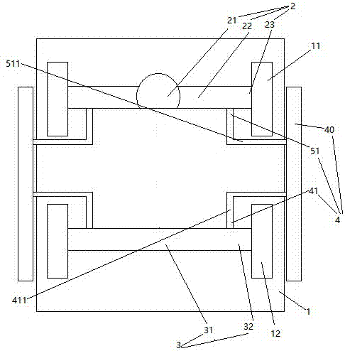
[0026] Embodiment one, see figure 1 , a side impact energy-absorbing automobile bridge assembly, including a vehicle frame 1, an axle housing 2, a front axle 3 and two side impact protection mechanisms 4.

[0027] Vehicle frame 1 is connected on axle housing 2 and front axle 3 by suspension mechanism.

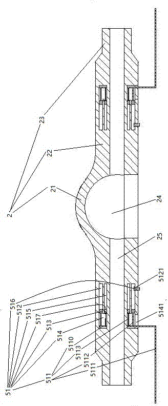
[0028] The axle housing 2 is provided with a reducer installation section 21 and two axle shaft installation sections 22 located on both sides of the reducer installation section. The free end of the axle shaft mounting section 22 is provided with a wheel joint 23 . The wheel joint 23 is connected with the rear wheel 11 .

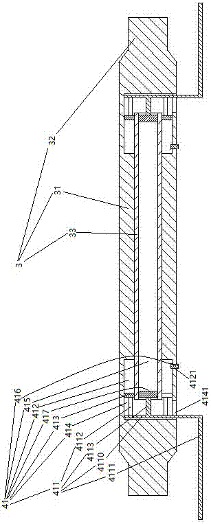
[0029] The front axle 3 includes a cross bar 31 and two suspension arms 32 located at both ends of the cross bar. The suspension arm 32 is connected to the front wheel 12 .

[0030] Two side impact protection mechanisms 4 are distributed on the left and right sides of the vehicle frame 1 . The side impact protection mechanism 4 includes a side protectio...

Embodiment 2

[0047] Embodiment two, the difference with embodiment one is:

[0048] see Figure 5 , the inner peripheral surface of the inner circular tube 5161 is provided with a vane 5168 for guiding the rotation of the seal head 516 of the axle housing portion when the fluid flows through the inner circular tube. The half shaft installation section 22 is also provided with a support frame 518 . The supporting frame 518 is rotatably connected with a connecting sleeve 519 through a plane bearing 5181 . The connecting sleeve 519 is connected with an annular blade 5191 . A limiting portion 5192 is formed between the annular blade 5191 and the connecting sleeve 519 . The blade 5191 is provided with an annular cutting edge 5193 . The annular cutting edge 5193 is aligned with the bottom wall 5163 . The outer diameter of the blade 5191 is equal to the inner diameter of the inner circular tube 5161.

[0049] During use, if the seal head 516 of the axle housing is sprayed out, before the an...


PUM


Abstract

The invention relates to a car crane span structure. A side-impact energy-absorbing type car crane span structure assembly comprises an axle case, a front axle, a car frame and two side-impact protective mechanisms located on the left side and the right side of the car frame, the car frame is connected to the axle case and the front axle through a suspension mechanism, the axle case is provided with a reducer mounting section and two half axle mounting sections located on the two sides of the reducer mounting section, a wheel connector is arranged at the free end of each half axle mounting section, each wheel connector is connected with a wheel, the front axle comprises a cross rod and two cantilevers located at the two ends of the cross rod, the cantilevers are connected with the wheels, each side-impact protective mechanism comprises side protecting rods extending in the front and rear directions, axle case part side-impact energy-absorbing structures arranged on the half axle mounting sections are arranged at one ends of the side protecting rods, and front shaft part side-impact energy-absorbing structures arranged on the cross rods are arranged at the other ends of the side protecting rods. The side-impact energy-absorbing type car crane span structure assembly which can absorb side-impact energy with no need of crumpling deformation of a car frame while side impact occurs is provided, and the problem of poor safety caused by the fact that a car body needs to crumple to absorb energy in side impact of an existing car is solved.

Description

technical field [0001] The invention relates to an automobile bridge, in particular to a side impact energy-absorbing automobile bridge assembly. Background technique [0002] The bridge frame of the car is composed of the frame, the rear axle (drive axle) supporting the frame and the front axle of the car (also known as the front axle, which is the steering axle). Both ends of the drive axle and the front axle are connected to the wheels, and the frame passes through the suspension Attached to the frame. [0003] The front axle of the car is used to install the front wheels, support the weight of the front of the car, and connect with the frame with the front suspension. In Chinese patent application number 2011201792654, the authorized announcement date is December 28, 2011, and promptly discloses a kind of automobile front axle of existing structure in the patent document of name " automobile front axle assembly ". The front axle of the automobile includes a cross bar a...

Claims


Application Information

Patent Timeline
IPC IPC(8): B60B35/16B60R19/42
CPCB60B35/006B60B35/121B60B35/163B60B35/166B60R19/42
Inventor 陈学福何伟
Owner 徐州国瑞汽车配件有限公司
Why Eureka
Try Eureka