Conveying device for hydraulic prop

A technology for conveying devices and hydraulic props, applied in the field of conveying devices and hydraulic props, can solve the problems of low utilization rate, scratched parts, different lengths, etc., and achieve the effect of improving utilization rate, saving time, and preventing bumps.

Inactive Publication Date: 2017-11-24
XUZHOU ZHONAN SCI & TECH CO LTD
View PDF8 Cites 2 Cited by
  • Summary
  • Abstract
  • Description
  • Claims
  • Application Information

AI Technical Summary

Problems solved by technology

[0002] Hydraulic props are one of the mining products with the largest consumption in coal mines. With the gradual strengthening of coal mine safety inspections by the country, the number of hydraulic props used has increased geometrically. In order to increase the production quantity of hydraulic props, manufacturers have also increased. The investment of staff and the increase of production time, but in the production process, it is found that when the hydraulic prop is transported from one process to the next, it is usually lifted by driving, but the driving can only lift one part at a time. This wastes a lot of time. Some manufacturers design carts for transportation, but the parts of the hydraulic prop are easy to be bumped during transportation, causing scratches on the surface of the parts, and the lengths of the parts are different, so the carts are usually only applicable One model part, so usage is also very low

Method used


Image

  • Conveying device for hydraulic prop
  • Conveying device for hydraulic prop
  • Conveying device for hydraulic prop

Examples


Embodiment Construction

[0019] The present invention will be further described below in conjunction with the accompanying drawings.

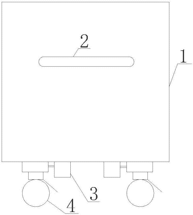
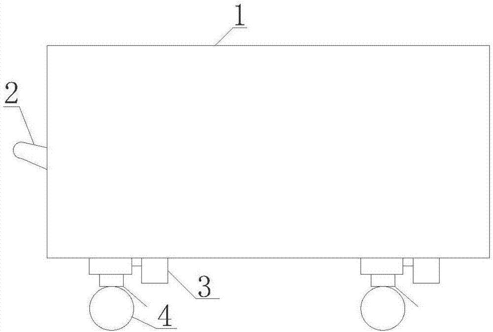
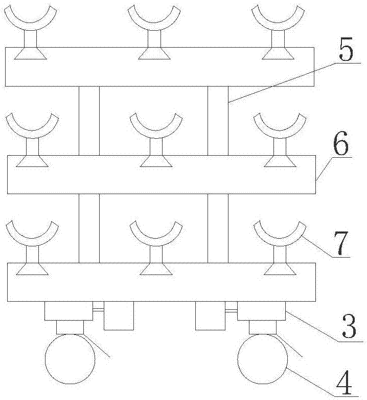
[0020] Such as Figure 1 to Figure 8 As shown, the conveying device of the hydraulic prop includes a box body 1, a handle 2, a control device 3, a roller 4, a pole 5, a panel device 6 and a support frame device 7, and the handle 2 is fixedly installed on one side of the rectangular box body 1 surface. Several support frame devices 7 are installed on several panel devices 6, at least two poles 5 are installed on the panel device 6, the control device 3 and the roller 4 are fixedly installed on the bottom surface of the panel device 6, and the control device 3 is composed of a shell I31, Shell II32, through hole I33, through hole II34, through hole III35, key I36, key II37, key III38, power supply 39 and single-chip microcomputer 310, shell I31 and shell II32 are snapped together to form the shell of the control device 3, the surface of shell I31 There are through holes...


PUM


Abstract

The invention provides a conveying device for a hydraulic prop and belongs to the technical field of a single hydraulic prop. The conveying device for the hydraulic prop comprises a box body, a handle, control devices, rollers, supporting rods, panel devices and supporting frame devices; the handle is fixedly mounted on one side of the surface of the oblong box body; the plurality of supporting frame devices are mounted on the plurality of panel devices; at least two supporting rods are mounted on the panel devices; the control devices and the rollers are fixedly mounted on the bottom surface of the panel device; the control devices comprise housings I, housings II, through holes I, through holes II, through holes III, keys I, keys II, keys III, power supplies and single chips; the panel devices comprise panels, guide rails and circular holes; and the supporting frame devices comprise protection pads, supporting frames, adjusting rods, screw rods, threaded grooves and dovetail grooves. The conveying device for the hydraulic prop has the advantages that multiple parts can be conveyed at one time without part surface scratches, the conveying device is suitable parts with any sizes, the use rate is high and the working efficiency of working personnel is enhanced.

Description

technical field [0001] The invention relates to a conveying device, in particular to a conveying device of a hydraulic prop, which belongs to the technical field of single hydraulic props. Background technique [0002] Hydraulic props are one of the mining products with the largest consumption in coal mines. With the gradual strengthening of coal mine safety inspections by the country, the number of hydraulic props used has increased geometrically. In order to increase the production quantity of hydraulic props, manufacturers have also increased. The investment of staff and the increase of production time, but in the production process, it is found that when the hydraulic prop is transported from one process to the next, it is usually lifted by driving, but the driving can only lift one part at a time. This wastes a lot of time. Some manufacturers design carts for transportation, but the parts of the hydraulic prop are easy to be bumped during transportation, causing scratch...

Claims


Application Information

Patent Timeline
Patent Type & Authority Applications(China)
IPC IPC(8): B62B3/02B62B3/10
CPCB62B3/02B62B3/104B62B2202/02
Inventor 陈亚东曹彦吉华红飞
Owner XUZHOU ZHONAN SCI & TECH CO LTD
Why Eureka
Try Eureka