Cylindrical cabin pre-compression tensioning heat dissipation structure and sealed cabin

A heat dissipation structure and pre-compression technology, applied in the direction of the hull, hull parts, ships, etc., can solve the problems of heat sinks scratching the cabin wall, components burning, low heat dissipation efficiency, etc.

Pending Publication Date: 2020-10-20
BOYA GONGDAO BEIJING ROBOT TECH CO LTD
View PDF0 Cites 2 Cited by
  • Summary
  • Abstract
  • Description
  • Claims
  • Application Information

AI Technical Summary

Problems solved by technology

[0002] Due to errors in processing and assembly, the current cylindrical cabin submersibles will cause the arc-shaped heat sink to not be in full contact with the wall...

Method used


Image

  • Cylindrical cabin pre-compression tensioning heat dissipation structure and sealed cabin
  • Cylindrical cabin pre-compression tensioning heat dissipation structure and sealed cabin
  • Cylindrical cabin pre-compression tensioning heat dissipation structure and sealed cabin

Examples


Embodiment 1

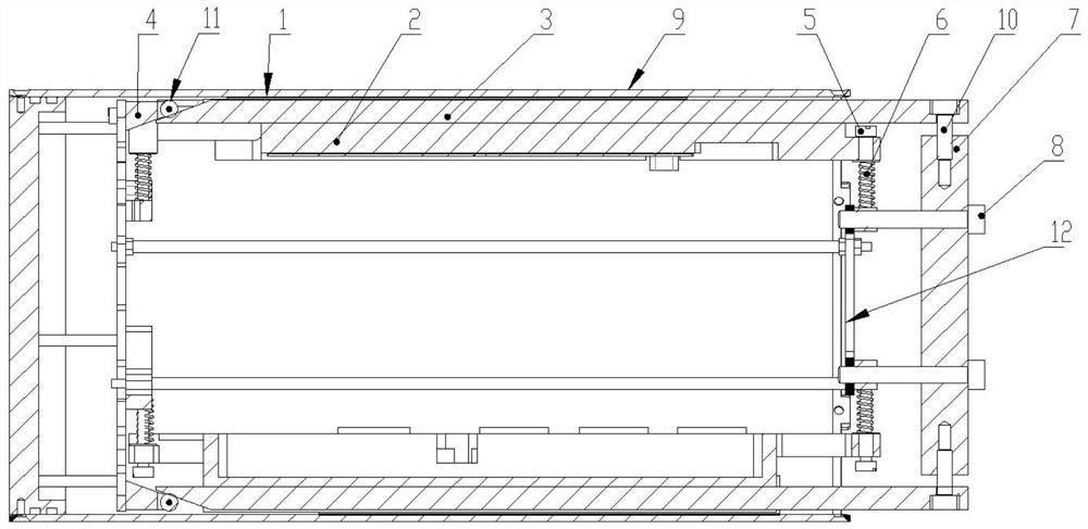
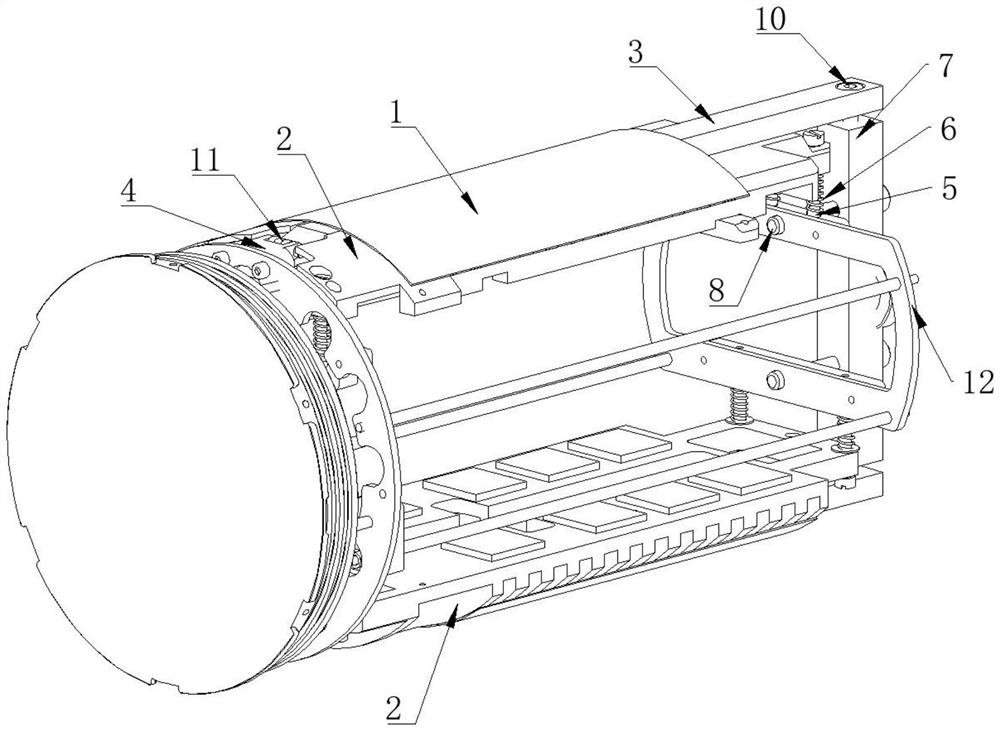
[0036] A pre-compressed and tensioned cooling structure for a cylindrical cabin. According to the characteristics of the cylindrical cabin, the pre-compression mechanism and the tensioning mechanism are designed, and the cooling plate is rationally arranged to greatly improve the heat dissipation efficiency and avoid the impact of the cooling plate on the inner wall of the cabin. scratches, such as figure 1 , figure 2 , image 3 , Figure 4 As shown, specifically set to the following structure:

[0037] The pre-compression and tightening heat dissipation structure of the cylindrical cabin includes a structural member 12 in the cabin, a cooling plate 2, a pre-compression mechanism and a tensioning mechanism. The heat dissipation surface of the cooling plate 2 is an arc surface to better match the cylindrical cabin 9 barrel wall.

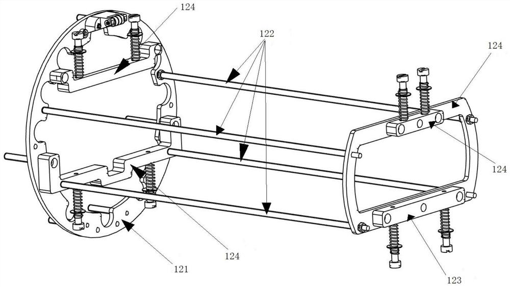
[0038] The cabin structure 12 includes a substantially circular rear end plate 121 , four support pipes 122 , an annular front end plate 123 and...

Embodiment 2

[0051] This embodiment further provides a cylindrical cabin airtight cabin on the basis of the above-mentioned embodiments, and particularly adopts the following structure:

[0052] This kind of cylindrical cabin airtight cabin includes a cylindrical cabin body 9, a ball top and the cylindrical cabin body pre-compression tension heat dissipation structure in embodiment 1, and the cylindrical cabin body pre-compression tension heat dissipation structure is inserted in the cylindrical cabin Inside the body 9, the spherical dome is installed on the head end of the cylindrical cabin 9 to encapsulate the pre-compressed tension heat dissipation structure of the cylindrical cabin. This kind of circular cabin body sealing cabin is more convenient when assembling the structure in the cabin, and can not scratch cylindrical cabin body 9 tube walls, and the cooling plate 2 and cylindrical cabin body 9 in the circular cabin body sealing cabin after assembling can Close contact, improve hea...


PUM


Abstract

The invention provides a cylindrical cabin pre-compression tensioning heat dissipation structure and a sealed cabin and relates to the technical field of underwater sealed cabins, and aims at solvingthe problems that in the prior art, a heat dissipation plate cannot be in complete contact with a cylinder wall, and the cylinder wall is scratched. According to the characteristics of a cylindrical cabin body, a pre-compression mechanism and a tensioning mechanism are additionally arranged in an internal cabin structural part, and the tensioning mechanism can push out a heat dissipation plate ina radial direction; in the pre-compression mechanism, a wedge-shaped base and a pre-compression rod are installed at the tail end and the head end of the internal cabin structural part respectively, the heat dissipation plate is arranged between the wedge-shaped base and the pre-compression rod, the pre-compression rod can move in the axial direction, and the head end of a pre-compression push rodis connected with the pre-compression rod and can move in the radial direction. The tail end of the pre-pressing push rod is a wedge-shaped head, and the pre-pressing push rod is movably connected with the heat dissipation face of the heat dissipation plate in a pressing mode. When the pre-pressing rod moves towards the wedge-shaped base, the wedge-shaped head inclined face of the pre-pressing push rod can be matched with the wedge-shaped base, and the pre-pressing push rod and the heat dissipation plate can move inwards in the radial direction. The heat dissipation plate can be reasonably arranged to improve the heat dissipation efficiency, and the heat dissipation plate is prevented from scratching the cylinder wall.

Description

technical field [0001] The invention relates to the technical field of an underwater airtight cabin, in particular to a cylindrical cabin body pre-compression tension heat dissipation structure and an airtight cabin. Background technique [0002] Due to errors in processing and assembly, the current cylindrical cabin submersibles will cause the arc-shaped heat sink to not be in full contact with the wall of the cabin, resulting in low heat dissipation efficiency, resulting in burnout of components, and scratches on the heat sink during assembly. Phenomenon of the tank wall. Contents of the invention [0003] The purpose of the present invention is to design a pre-compressed and tightened heat dissipation structure of a cylindrical cabin and a sealed cabin. According to the characteristics of the cylindrical cabin, the pre-compression mechanism and the tension mechanism are designed, and the cooling plates are rationally arranged to greatly improve the heat dissipation effi...

Claims


Application Information

Patent Timeline
IPC IPC(8): B63C11/52B63G8/00B63B3/14
CPCB63B3/14B63C11/52B63G8/001
Inventor 熊明磊陈龙冬刘夏
Owner BOYA GONGDAO BEIJING ROBOT TECH CO LTD
Why Eureka
Try Eureka