Automatic conveying mechanism of illuminating fluorescent tubes with automatic adjustment mechanism

A fluorescent tube and automatic conveying technology, which is applied in the direction of conveyors, conveyor objects, conveyor control devices, etc., can solve the problems of low efficiency and poor effect, and achieve the effect of high efficiency, good effect and easy access

Inactive Publication Date: 2017-11-24
FOSHAN KERUIFEI NEW ENERGY TECH CO LTD
View PDF0 Cites 6 Cited by
  • Summary
  • Abstract
  • Description
  • Claims
  • Application Information

AI Technical Summary

Problems solved by technology

[0002] The existing installation process of fluorescent tubes is generally manual installation. The tubes are usually placed in a carrying box, and the tubes are manually transported to the installation place, and manually picked up and installed one by one. The efficiency is low and the effect is poor.

Method used


Image

  • Automatic conveying mechanism of illuminating fluorescent tubes with automatic adjustment mechanism
  • Automatic conveying mechanism of illuminating fluorescent tubes with automatic adjustment mechanism
  • Automatic conveying mechanism of illuminating fluorescent tubes with automatic adjustment mechanism

Examples


Embodiment

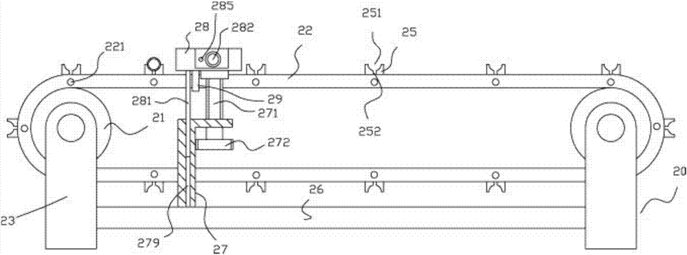
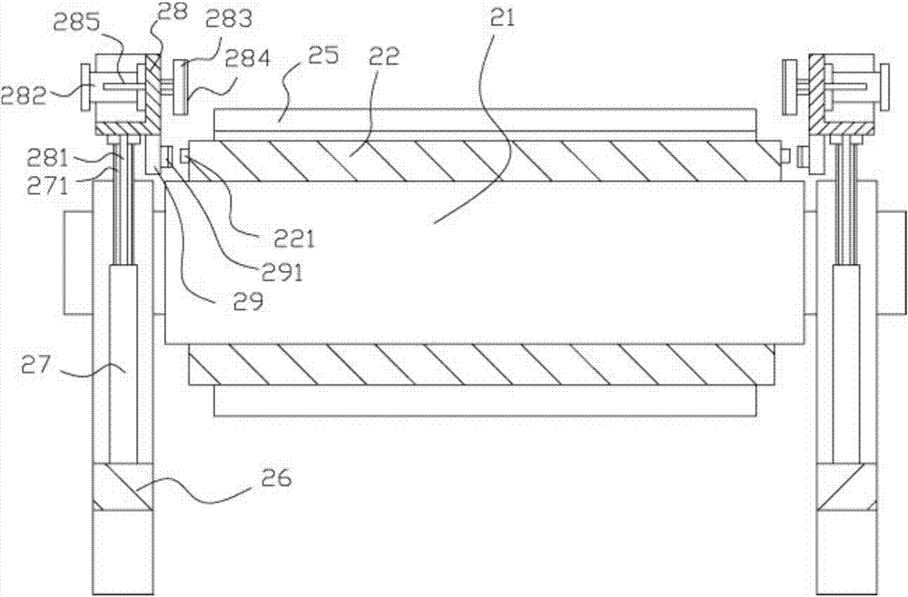
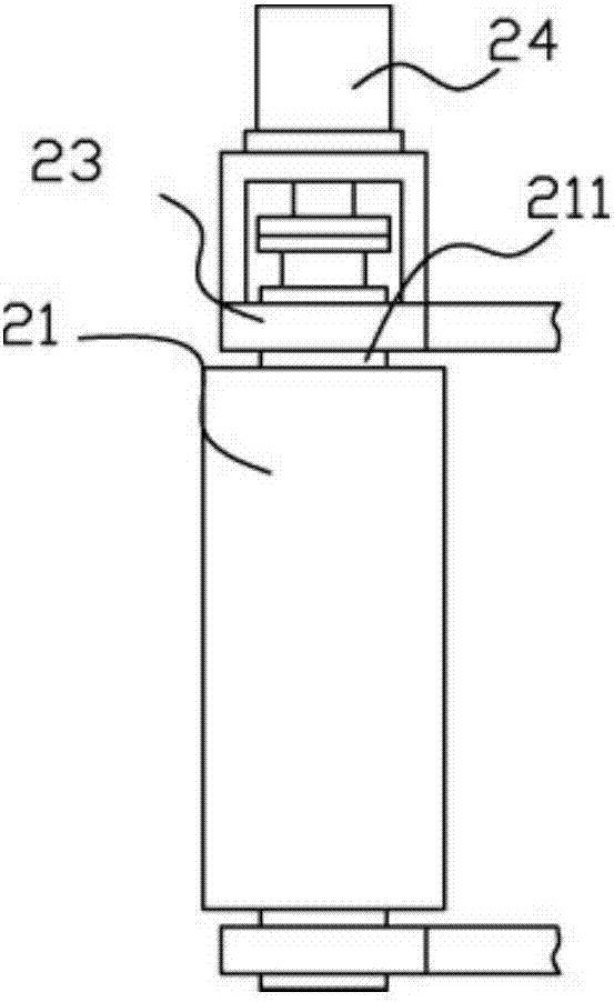
[0017] Example: see Figure 1 to Figure 3 As shown, an automatic conveying mechanism for lighting fluorescent tubes with an automatic adjustment mechanism includes a conveying frame 20, the left and right ends of the conveying frame 20 are hinged with transmission rollers 21, and the conveyor belt 22 is tensioned on the two transmission rollers 21, wherein One end of a transmission roller 21 is formed with a raised column 211, and the raised column 211 stretches out from the support leg 23 of the conveyor frame 20 and is connected with the output shaft of the transmission motor 24 fixed on the support leg 23 through a coupling. A plurality of lamp tube placement blocks 25 are fixed on the outer wall surface of 22, and a mounting groove 251 is formed on the outer wall surface of the lamp tube placement block 25;

[0018] Described delivery frame 20 comprises four supporting legs 23, is provided with intermediate beam 26 between two supporting legs 23 on the same side, and the t...


PUM


Abstract

The invention discloses an automatic conveying mechanism for lighting fluorescent tubes with an automatic adjustment mechanism, which includes a conveying frame. Drive rollers are hinged at the left and right ends of the conveying frame. The conveyor belt is stretched on the two driving rollers. One end is formed with a protruding column, which extends out of the legs of the conveyor frame and is connected with the output shaft of the transmission motor fixed on the leg through a coupling, and a plurality of lamp tube placement blocks are fixed on the outer wall of the conveyor belt , the outer wall surface of the lamp tube placement block is formed with an installation groove; the conveying frame includes four legs, and an intermediate beam is arranged between the two legs on the same side, and the two ends of the intermediate beam are fixed on the two legs Above, the middle top surface of the middle beam is fixed with a vertical support frame, and the top plate of the vertical support frame is screwed with an adjusting stud. It can automatically transport multiple lamp tubes and automatically adjust the placed lamp tubes. It has a high degree of automation, is convenient for manual picking, does not need manual handling, and has high efficiency and good effect.

Description

Technical field: [0001] The invention relates to the technical field of lighting equipment manufacturing, and more specifically relates to an automatic delivery mechanism for lighting fluorescent tubes with an automatic adjustment mechanism. Background technique: [0002] The existing fluorescent tube installation process generally adopts manual installation, and its lamp tubes are generally placed in the carrying box, manually transported to the installation place, manually picked up and installed one by one, its efficiency is low, and the effect is poor. Invention content: [0003] The purpose of the present invention is to address the deficiencies of the prior art, and to provide an automatic delivery mechanism for lighting fluorescent tubes with an automatic adjustment mechanism, which can automatically transport multiple tubes and automatically adjust the placed tubes, and its automation High degree, easy to take manually, no manual handling, high efficiency and good ...

Claims


Application Information

Patent Timeline
Patent Type & Authority Applications(China)
IPC IPC(8): B65G47/24B65G23/04B65G15/58B65G43/08
CPCB65G47/24B65G15/58B65G23/04B65G43/08B65G2201/0276B65G2203/0225
Inventor 叶芳
Owner FOSHAN KERUIFEI NEW ENERGY TECH CO LTD
Why Eureka
Try Eureka