

Lifting machine with heat preservation function
A hoist and function technology, applied in the field of material transmission equipment, can solve problems such as unreasonable use of time
- Summary
- Abstract
- Description
- Claims
- Application Information
AI Technical Summary
Problems solved by technology
Method used
Image

Examples
Embodiment Construction
[0030] Specific embodiments of the present invention will be described in detail below in conjunction with the accompanying drawings. It should be understood that the specific embodiments described here are only used to illustrate and explain the present invention, and are not intended to limit the present invention.
[0031] In the present invention, unless otherwise specified, the orientation words included in the term such as "up, down, left, right, front, back, inside and outside" only represent the orientation of the term in the normal use state, or the common name understood by those skilled in the art. , and should not be construed as a limitation of this term.
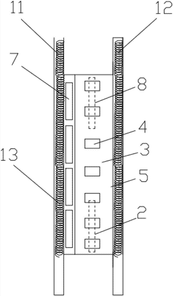
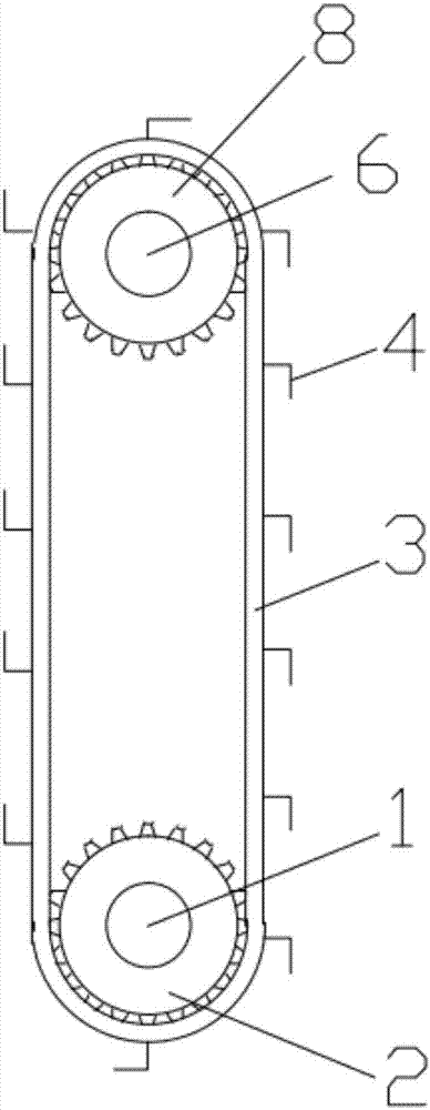
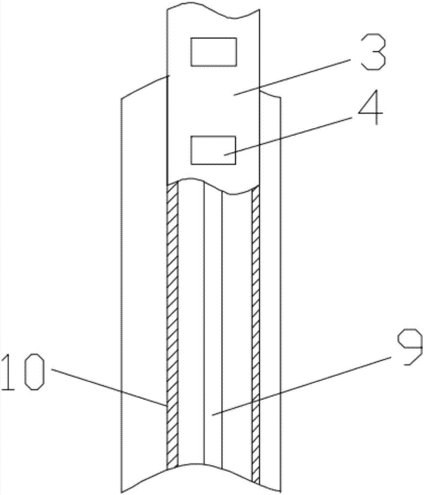
[0032] see Figure 1-3 The hoist shown has the function of heat preservation, and the hoist includes: a left support plate 11, a right support plate 12, ring tracks fixed on the left support plate 11 and the right support plate 12 on both sides, and driving wheels 2. The driven wheel 8 and the driving mechani...
PUM
 Abstract
Description
Claims
Application Information