Honeycomb core mounting construction method

A construction method and honeycomb core technology, which is applied to building components, floors, buildings, etc., can solve the problems of inconvenient follow-up construction and low reliability of honeycomb core connection, and achieve the effect of increasing positional stability

Active Publication Date: 2017-11-24
CHINA MCC5 GROUP CORP
View PDF6 Cites 2 Cited by
  • Summary
  • Abstract
  • Description
  • Claims
  • Application Information

AI Technical Summary

Problems solved by technology

[0004] Aiming at the problems of inconvenient follow-up construction and low connection reliability of honeycomb cores in the method for constraining honeycomb cores in the prior art proposed above, the present invention provides a construction method for installing honeycomb cores

Method used


Image

  • Honeycomb core mounting construction method
  • Honeycomb core mounting construction method
  • Honeycomb core mounting construction method

Examples


Embodiment 1

[0042] Such as image 3 As shown, a construction method for installing a honeycomb core, including step S1: erecting a formwork; step S3: placing the honeycomb core on the formwork, and step S2: setting bottom constraints for the honeycomb core on the formwork;

[0043] The step S2 is located between the steps S1 and S3 or after the step S3;

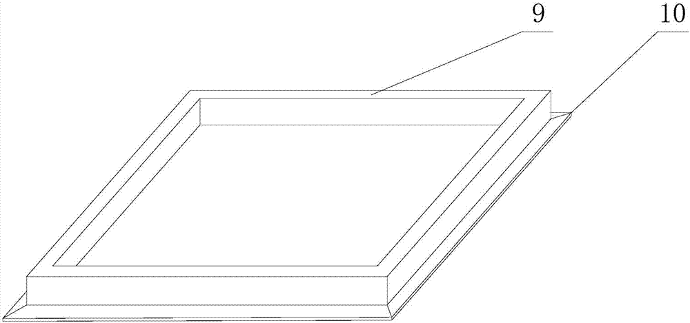
[0044] When step S2 is located between steps S1 and S3, step S2 is to set the surrounding edge 9 around the installation position of the honeycomb core, so that after the honeycomb core is placed at the installation position, all sides around the honeycomb core are connected to the inside of the surrounding edge 9 touch;

[0045] When the step S2 is located after the step S3, the step S2 is to set the surrounding edge 9 around the honeycomb core, and each side of the honeycomb core is in contact with the inner side of the surrounding edge 9;

[0046] The connection relationship between the surrounding edge 9 and the template is a detac...

Embodiment 2

[0049] This embodiment is further limited on the basis of the technical solution provided in embodiment 1, as image 3 As shown, as a specific implementation scheme of the surrounding edge 9, the surrounding edge 9 is a frame-like structure surrounded by wooden boards, and the connection mode between the surrounding edge 9 and the formwork adopts any one or several of the following methods : Tenon connection, iron nail connection, screw connection;

[0050] When using iron nails or screws, the iron nails and screws are embedded in the surrounding edge 9 upwards from the bottom of the formwork. In this solution, the surrounding edge 9 can be made of waste templates, which has the characteristics of convenient material acquisition and low cost; the specific solution of the above detachable connection method has low cost and high realization efficiency. Specifically, when tenon joints are used, a circular blind hole can be drilled on the upper side of the formwork as a tenon gro...

Embodiment 3

[0054] Such as Figure 1 to Figure 3 As shown, this embodiment is further defined on the basis of the technical solution provided in Embodiment 1, as a step for implementing vertical constraints on the honeycomb core, it also includes step S4: setting top constraints for the honeycomb core , the top constraint is used to apply downward compressive stress to the top surface of the honeycomb core.

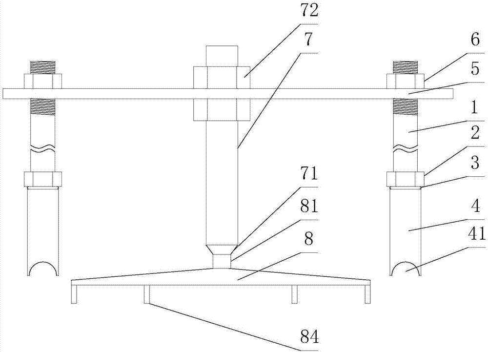
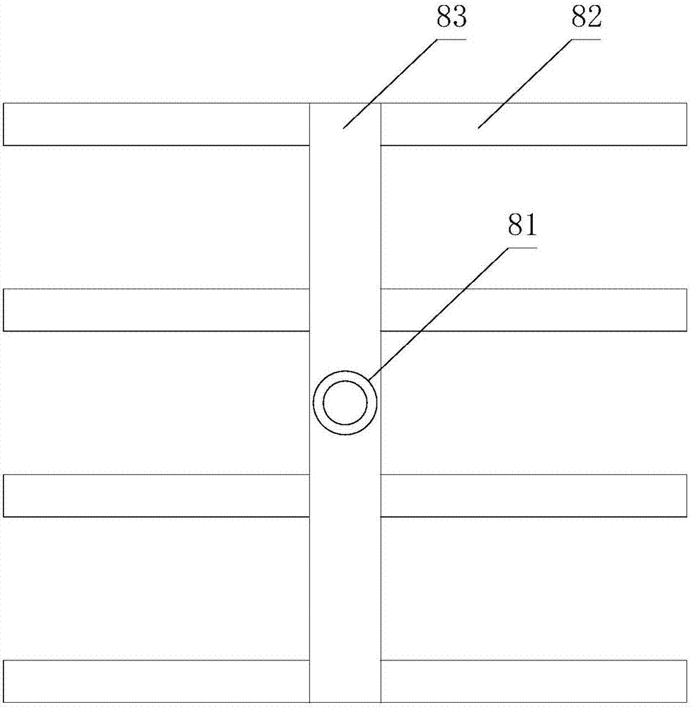
[0055] As a specific implementation of the top constraint, the top constraint includes a frame body connected to the floor steel mesh, a compression bar 7 connected to the frame body at the upper end, and a compression plate 8 for placing on the upper surface of the honeycomb core;

[0056] Described frame body comprises vertical rod and crossbeam 5, and described vertical rod comprises connecting seat 4 and column 1, and described connecting seat 4 is provided with internally threaded hole, and the lower end of column 1 is threadedly connected with internally threaded hole, and desc...


PUM


Abstract

The invention discloses a honeycomb core mounting construction method. The honeycomb core mounting construction method comprises the steps that S1, a mold plate is erected; and S3, a honeycomb core is placed on the mold plate, and the S2 is further included and comprises that on the mold plate, a bottom restraint is arranged for the honeycomb core, wherein the S2 is executed between the S1 and the S3 or executed after the S3; when the S2 is executed between the S1 and the S3, the S2 is executed as follows, a surrounding edge is arranged on the periphery of the mounting position of the honeycomb core, and therefore after the honeycomb core is placed on the mounting position, all sides of the periphery of the honeycomb core make contact with the inner side of the surrounding edge; when the S2 is executed after the S3, the S2 is executed as follows, the surrounding edge is arranged on the periphery of the honeycomb core, and all sides of the honeycomb core make contact with the inner side of the surrounding edge; the surrounding edge is detachably connected with the mold plate. According to the construction method, the honeycomb core can be reliably restrained, and meanwhile, the dependency of stability of the position of the honeycomb core on the connecting strength of the honeycomb core and a reinforcing mesh can be weakened.

Description

technical field [0001] The invention relates to the technical field of building construction methods, in particular to a construction method for installing honeycomb cores. Background technique [0002] Among the existing building forms, the honeycomb core floor has the following advantages: first, it is convenient for construction, and the mandrel can be placed directly, reducing the amount of concrete, shortening the maintenance time, and can also speed up the construction progress and shorten the construction period; second, it has good bearing performance , suitable for large spans; the third is that when the same bearing capacity is achieved, less concrete and other materials are used, so its own weight is also small, the economy is better, the plate thickness is thinner than other structures, and the net height of the floor can be increased; the fourth is relative Compared with other rib beam structures, the bottom plate makes the honeycomb core floor flat and beautifu...

Claims


Application Information

Patent Timeline
Patent Type & Authority Applications(China)
IPC IPC(8): E04B5/18
CPCE04B5/18
Inventor 吕沛川蒋毅罗刚
Owner CHINA MCC5 GROUP CORP
Why Eureka
Try Eureka