Bidirectional displacement hydraulic motor with speed limiting device

A speed limiting device and hydraulic motor technology, which is applied in the field of hydraulic motors and bidirectional displacement hydraulic motors, can solve problems such as motor impact, equipment safety accidents, and motor damage, and achieve the effect of preventing damage and improving safety

Active Publication Date: 2017-11-24
XUZHOU COLLEGE OF INDAL TECH
View PDF4 Cites 4 Cited by
  • Summary
  • Abstract
  • Description
  • Claims
  • Application Information

AI Technical Summary

Problems solved by technology

If you reduce the displacement of the hydraulic motor while keeping the flow rate of the hydraulic motor constant, the speed of the hydraulic motor will increase. Therefore, no matter how small the flow rate is, when the motor displacement is very small or close to zero displacement, the speed of the motor will still be extremely high, which will inevitably cause the centrifugal force of the rotating components of the motor to increase rapidly. As a result, the relative movement speed of several friction pairs such as the plunger and the cylinder body increases rapidly, and the wear increases, exceeding the physical limit of the motor components, resulting in damage to the motor
[0006] In the prior art, the flow of the motor is completely cut off by switching the reversing valve, etc., so that it stops rotating. When the motor is stationary, its displacement is adjusted to the reverse direction, and then the oil circuit is connected to make it rotate reversely. This is easy to cause impact on the motor, and the control program is complicated; and if the reverse variable operation is performed on the motor without cutting off the flow of the motor, it will cause damage to the motor or even a safety accident of the equipment

Method used


Image

  • Bidirectional displacement hydraulic motor with speed limiting device
  • Bidirectional displacement hydraulic motor with speed limiting device
  • Bidirectional displacement hydraulic motor with speed limiting device

Examples


Embodiment Construction

[0023] The present invention will be further described below in conjunction with accompanying drawing.

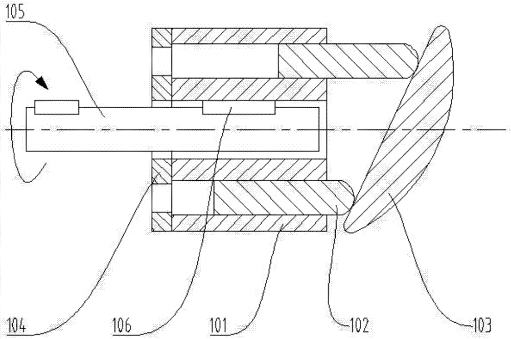
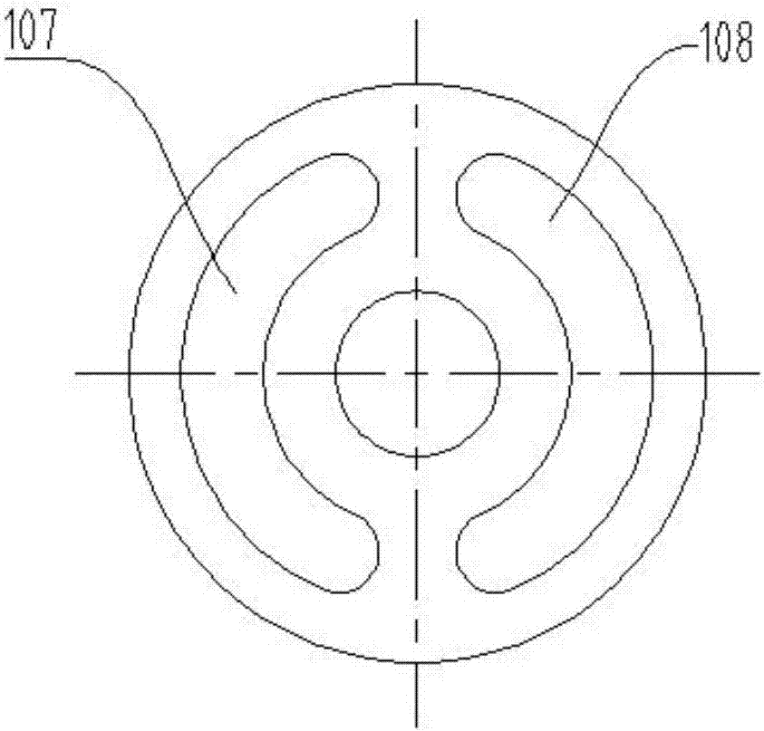
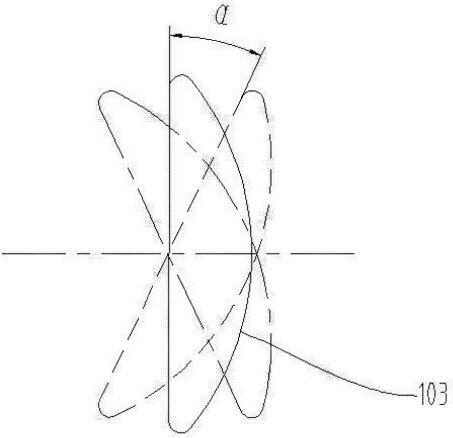
[0024] Such as Figures 3 to 5 As shown, a two-way displacement hydraulic motor with a speed limiting device includes a motor body 1 and a casing 2. The motor body 1 includes a cylinder block 101, an output shaft 105, a plunger 102, a swash plate 103, and a valve plate 104. The cylinder block 101 distributes several round holes evenly along the radial direction, the plunger 102 is installed in the round hole, and one end of the plunger 102 acts on the swash plate 103; the cylinder body 101 is closely matched with the distribution plate 104, and the distribution plate 104 has an oil hole 107, the output shaft 105 is connected to the cylinder body 101 through a key 106; a speed limiting device is installed in the casing 2, and the speed limiting device includes a bypass valve 3 and a lever mechanism 4, and a roller I32 is installed at the lower end of the spool 31 of the bypa...


PUM


Abstract

The invention discloses a bidirectional displacement hydraulic motor with a speed limiting device. The speed limiting device is installed in a shell and comprises a bypass valve and a lever mechanism. A first roller is installed at the lower end of a valve element of the bypass valve. A spring is arranged between the upper end of the valve element and a valve housing. The lever mechanism is hinged to the portion, beside the bypass valve, of the shell. An ejector rod is arranged beside the hinge point of a lever. A second roller is connected to the bottom of the ejector rod. One end of the lever is in contact with the first roller at the bottom of the bypass valve. When a tilting tray is vertical, the top of the tilting tray is in contact with the second roller. The bypass valve can be opened automatically through the speed limiting device when the motor displacement approximates to zero, so that oil is incapable of flowing through the hydraulic motor, the motor is protected against overspeed in case of small displacement and also protected against damage caused by overspeed, and safety of the motor is effectively improved when the running direction is switched.

Description

technical field [0001] The invention relates to a hydraulic motor, in particular to a bidirectional displacement hydraulic motor with a speed limiting device, and belongs to the technical field of hydraulic control equipment. Background technique [0002] A hydraulic motor is a hydraulic component that converts the pressure energy of a hydraulic medium into mechanical energy in the form of rotational motion. Common hydraulic motors can be divided into gear type, vane type and plunger type according to the structural form. The plunger motor can be divided into radial and axial according to the positional relationship between the plunger and the transmission shaft. In practical applications, axial piston motors are mostly used. Generally, hydraulic motors have two main working oil ports. When one oil port enters high-pressure oil and the other oil port discharges oil, the output shaft of the motor rotates in one direction. Change the oil inlet and outlet ports, and the moto...

Claims


Application Information

Patent Timeline
Patent Type & Authority Applications(China)
IPC IPC(8): F03C1/06F03C1/40
CPCF03C1/0613F03C1/0681F03C1/0686
Inventor 李建松张文婷
Owner XUZHOU COLLEGE OF INDAL TECH
Why Eureka
Try Eureka