High-precision guide rail straightness calibration structure and method

A straightness and high-precision technology, used in linear motion bearings, angle/taper measurement, bearings, etc., to solve the problems of complex equipment structure, adjustable position, few directions to meet work requirements, and single adjustment and control means.

Pending Publication Date: 2017-11-24
GUANGDONG UCAN ROBOT TECH CO LTD
View PDF11 Cites 6 Cited by
  • Summary
  • Abstract
  • Description
  • Claims
  • Application Information

AI Technical Summary

Problems solved by technology

[0005] Although the above-mentioned regulators have their own characteristics, they all have some defects. The overall equipment adjustment accuracy is low, and it is difficult to adapt to occasions with high precision requirements. The use of general-purpose levers, sliders and other mechanisms has relatively large errors, and the adjustment control means Single, adjustable position, less directions to meet work needs, poor adaptability, complex equipment structure, large maintenance, etc.
In addition, the current method of adjusting the straightness of the guide rail is generally to rely on the machine tool to process a surface, then push the reference surface of the guide rail up, and tighten the guide rail with screws from the side, so that the installation method feels that the guide rail is straight. In fact, this method is completely It depends on the machining accuracy of the machine tool to ensure the installation accuracy of the guide rail. If the machining accuracy meets the requirements, it is impossible to install a high-precision guide rail.
This is its disadvantage, and the highest precision of this installation method may be 0.01mm

Method used


Image

  • High-precision guide rail straightness calibration structure and method
  • High-precision guide rail straightness calibration structure and method
  • High-precision guide rail straightness calibration structure and method

Examples


Embodiment 1

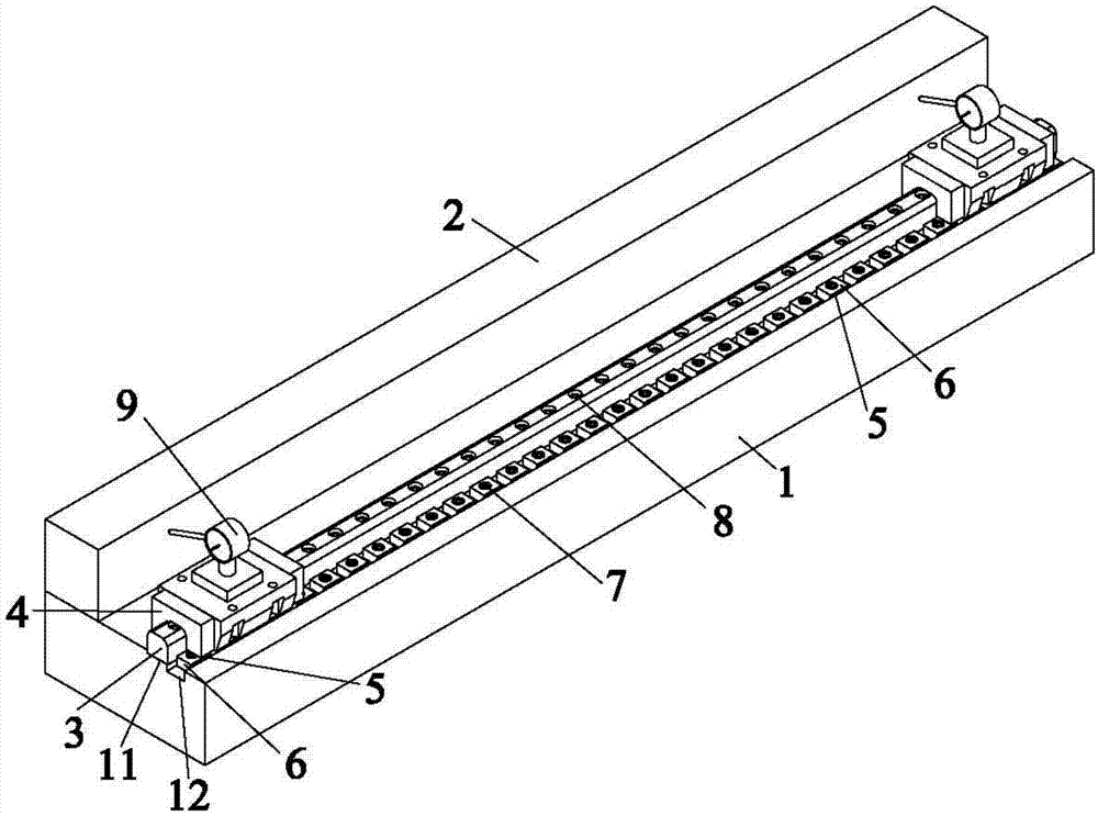
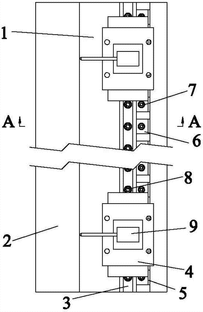
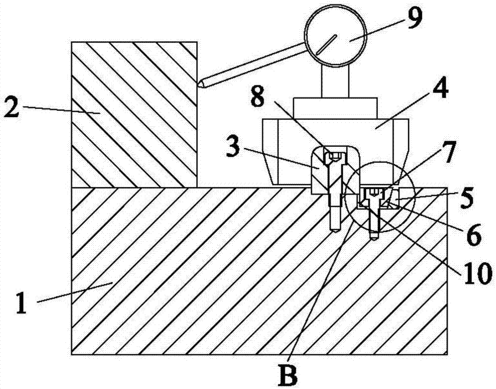
[0025] Example 1, such as Figure 1~4 As shown, a calibration structure for the straightness of a high-precision guide rail includes a base 1, a marble parallel ruler 2, a guide rail 3, a slider 4, a wedge 5, a top tightening block 6, an adjusting screw 7 and a fixing screw 8, and the marble parallel ruler 2 Installed on one side of the base 1, the base 1 is provided with an installation groove 11 and an adjustment groove 12 connected with the installation groove 11, the guide rail 3 is locked in the installation groove 11 by the fixing screw 8, and the guide rail 3 is closely attached to the installation groove 11 On the side wall, the slider 4 is slidably arranged on the guide rail 3, and a dial indicator 9 for calibrating the straightness of the guide rail 3 is placed on the top of the slider 4. The wedge 5 and the top tightening block 6 are all installed in the adjustment groove 12, and the top tightening block One end surface of 6 abuts against the guide rail 3 , the othe...

Embodiment 2

[0029] Embodiment 2, realize the calibration method to guide rail straightness by the structure of embodiment 1, comprise the following steps:

[0030] 1) Install the marble parallel ruler 2 on the side of the base 1, make the marble parallel ruler 2 and the guide rail 3 in a parallel state as much as possible, and place the dial gauge 9 on the slider 4 slidingly connected with the guide rail 3, so that the dial gauge 9 The measuring head is in contact with the side wall of the marble parallel ruler 2. At this time, measure the reading at point A of one end of the marble parallel ruler 2, then move the slider 4 to the other end, and measure the marble parallel ruler 2 without moving at the position of the dial indicator 9. The value of point B at one end, if the readings of points A and B are consistent, it means that the straightness of the marble has been calibrated, if the readings of points A and B are inconsistent, it means that the straightness of the marble is not calibr...


PUM


Abstract

The invention discloses a high-precision guide rail straightness calibration structure. The high-precision guide rail straightness calibration structure comprises a base, a marble parallel ruler, a guide rail, slide blocks, wedge blocks, tightly-jacking blocks, adjusting screws and fixing screws. The marble parallel ruler is mounted at one side of the base. A mounting groove and an adjustment groove are formed in the base, wherein the adjustment groove is connected with the mounting groove. The guide rail is locked in the mounting groove through the fixing screws and closely attached to the side wall of the mounting groove. The slide blocks are arranged on the guide rail in a sliding manner. A dial indicator is mounted at the top of each slide block, wherein the dial indicators are used for calibrating the straightness of the guide rail. The wedge blocks and the tightly-jacking blocks are all mounted in the adjustment groove. One end face of each tightly-jacking block abuts against the guide rail, and the other end face of each tightly-jacking block abuts against one end face of the corresponding wedge block in a jacking manner; and the other end face of each wedge block is closely attached to the side wall of the adjustment groove. By means of the calibration structure, the requirement for a face, keeping to the side, of a machined workpiece is not high; the straightness of the guide rail can be represented with data; the straightness of the guide rail can be adjusted within the range of 0.002 mm; and the high-precision guide rail straightness calibration structure is applicable to a machine tool high in precision requirement. In addition, the invention further discloses a guide rail straightness calibration method.

Description

technical field [0001] The invention relates to the technical field of guide rail installation, in particular to a calibration structure and method for the straightness of a high-precision guide rail. Background technique [0002] Nowadays, many kinds of advanced precision measuring equipment provide a lot of convenience for automobile, aviation, national defense, engineering, mold, electronics, information technology, medical and other industries, and promote the development of various industries. [0003] Chinese invention patent 200810243297.9 discloses a guide rail straightness adjustment device, which includes a cam or eccentric wheel adjustment mechanism that can exert a stepless, continuous and controllable extrusion force on the guide rail or beam, and a fixing device for fixing the adjustment mechanism. The adjustment mechanism includes a cam, a slider, a slider moving guide rail, and a set screw for fixing the slider in the cam slider moving guide rail. The blocks...

Claims


Application Information

Patent Timeline
IPC IPC(8): F16C29/00F16C41/00G01B5/25
CPCF16C29/001F16C41/00G01B5/25F16C2322/39
Inventor 王俊锋唐凌志王海涛唐进龙张健李敏
Owner GUANGDONG UCAN ROBOT TECH CO LTD
Why Eureka
Try Eureka