Test stand for detecting drawing and inserting force of control rod guide tube of fuel assembly

A technology of control rod guide tube and fuel assembly, which is applied in nuclear reactor monitoring, reactor, nuclear power generation, etc.

Inactive Publication Date: 2017-11-24
NUCLEAR POWER INSTITUTE OF CHINA
View PDF4 Cites 2 Cited by
  • Summary
  • Abstract
  • Description
  • Claims
  • Application Information

AI Technical Summary

Problems solved by technology

[0004] Aiming at the above-mentioned problem in the prior art that there is no equipment capable of real-time detection of the pulling force of the control rod when it is inserted or pulled up in the guide tube, the present invention provides a meth

Method used


Image

  • Test stand for detecting drawing and inserting force of control rod guide tube of fuel assembly
  • Test stand for detecting drawing and inserting force of control rod guide tube of fuel assembly
  • Test stand for detecting drawing and inserting force of control rod guide tube of fuel assembly

Examples


Embodiment 1

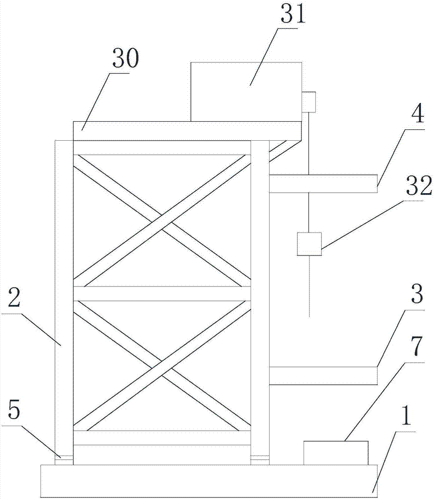
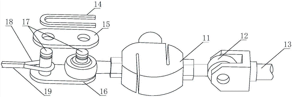
[0048] Such as Figure 1 to Figure 4 As shown, a test bench for detecting the insertion force of the fuel assembly control rod guide tube includes a bench, a lifting unit 31 installed on the bench, a second pull rope 19 wound on the lifting unit 31, connected to the first The measuring unit 32 on the two stay ropes 19 also includes a mobile unit 30, the lifting unit 31 is fixed on the mobile unit 30, the mobile unit 30 is installed on the stand, and the mobile unit 30 is used to change the lifting unit 31 position on the horizontal plane.

[0049] In this embodiment, in the test bench structure provided above, the bench is used as the frame of the test bench, the lifting unit 31 is used to lift the control rod by the second stay rope 19, and the measuring unit 32 is used as the intermediate connection between the lifting unit 31 and the control rod In the process of lifting the control rod, the force on the measuring unit 32 can display in real time the magnitude of the lifti...

Embodiment 2

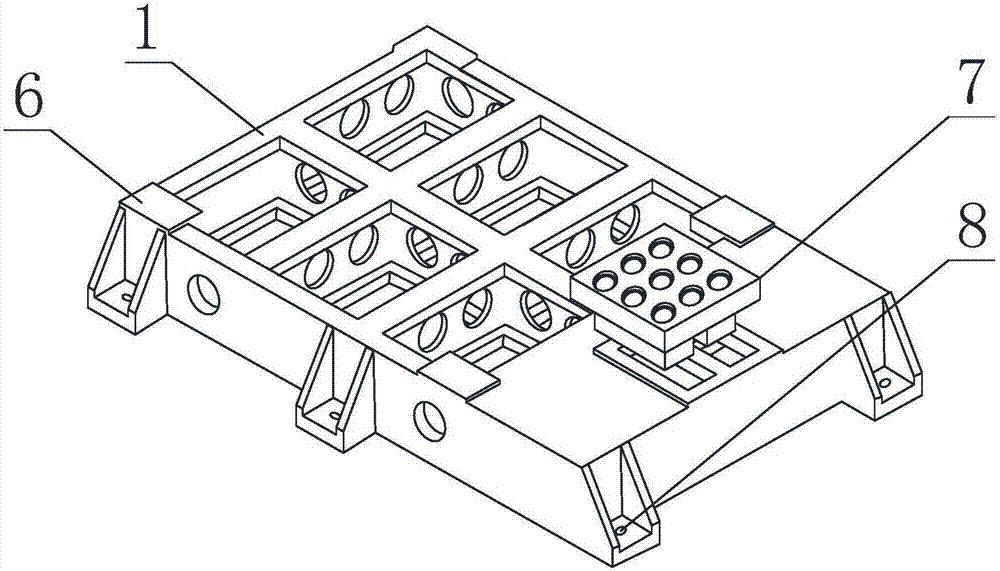
[0052] The present embodiment is further limited on the basis of embodiment 1, as Figure 1 to Figure 4 As shown, the stand includes a column 2, an upper plate 3 and a lower plate 7, the upper plate 3 is fixed on the side of the column 2, and the lower plate 7 is located directly below the upper plate 3;

[0053] The upper plate 3 is provided with a plurality of upper plate holes whose axial directions are all located in the vertical direction, and the lower plate 7 is provided with lower plate holes equal in number to the number of upper plate holes, and in the vertical direction, the lower plate holes are the same as the upper plate holes. The positions of the holes on the upper plate are in one-to-one correspondence;

[0054]The upper plate hole is a through hole that runs through the upper and lower ends of the upper plate 3, and the lower plate hole is a blind hole or a through hole that runs through the upper and lower ends of the lower plate 7 and is in the shape of a s...

Embodiment 3

[0062] This embodiment is further limited on the basis of Embodiment 1. In this embodiment, the above mobile unit 30 can be implemented by installing an X slide rail whose length direction is located in the X direction on the upper end of the stand, and installing on the X slide rail An X slide plate, the X slide plate is driven by a servo motor or a hydraulic cylinder, so that the X slide plate can move along the length direction of the X slide rail, if a servo motor is used, it can be driven by a threaded rod; further, on the X slide plate Then set the Y slide rail whose length direction is in the Y direction, install a Y slide plate on the Y slide rail, and the Y slide plate is driven by a servo motor or hydraulic cylinder, so that the Y slide plate can move along the length direction of the Y slide rail. When the servo motor is driven, it can be driven by a threaded rod; the length direction of the above Y slide rail is perpendicular to the length direction of the X slide r...


PUM


Abstract

The invention discloses a test stand for detecting drawing and inserting force of a control rod guide tube of a fuel assembly. The test stand comprises a stand rack, a lifting unit arranged on the stand rack, a second stay rope coiling on the lifting unit, a measurement unit connected with the second stay rope, and a mobile unit; the lifting unit is fixed on the mobile unit, the mobile unit is arranged on the stand rack, and the mobile unit is used for changing the position of the lifting unit on a horizontal plane. The test stand can better complete the detection of drawing and inserting force when a control rod is downwardly inserted in a guide tube or upwardly drawn from the guide tube.

Description

technical field [0001] The invention relates to the technical field of reactor fuel assembly detection, in particular to a test bench for detecting the pulling force of a fuel assembly control rod guide tube. Background technique [0002] The reactor fuel assembly is mainly composed of upper tube base, lower tube base, positioning grid, control rod guide tube and fuel rods. Among them, the basic functions of control rod guide tube are: (1) to provide structural continuity; (2) to provide fuel Relevant components provide insertion channels; (3) provide hydraulic buffering for the end of the falling stroke of the control rods during the emergency shutdown of the reactor, so as to prevent excessive impact when the control rods fall. [0003] The existing situation is that when the control rod is inserted or pulled up in the guide tube, there is no device that can detect the magnitude of its pulling force in real time. In this way, in the actual operation process, there may be ...

Claims


Application Information

Patent Timeline
IPC IPC(8): G21C17/10
CPCG21C17/10Y02E30/30
Inventor 吴婧和川李斌彭小明许贵平
Owner NUCLEAR POWER INSTITUTE OF CHINA
Why Eureka
Try Eureka