
Grinding belt machine

A technology of a belt grinder and a frame, which is applied in the field of belt grinders and can solve problems such as energy waste of the belt grinder

Pending Publication Date: 2017-11-28
ANHUI CHIZHOU WEISS ELECTROMECHANICAL
View PDF0 Cites 2 Cited by
  • Summary
  • Abstract
  • Description
  • Claims
  • Application Information

AI Technical Summary

Problems solved by technology

The existing abrasive belt machine runs at high speed when grinding the workpiece, but when the operator removes the workpiece, the abrasive belt machine still runs at high speed, which causes unnecessary waste of energy for the abrasive belt machine

Method used


Image

  • Grinding belt machine

Examples


Embodiment Construction

[0011] Specific embodiments of the present invention will be described in detail below in conjunction with the accompanying drawings.

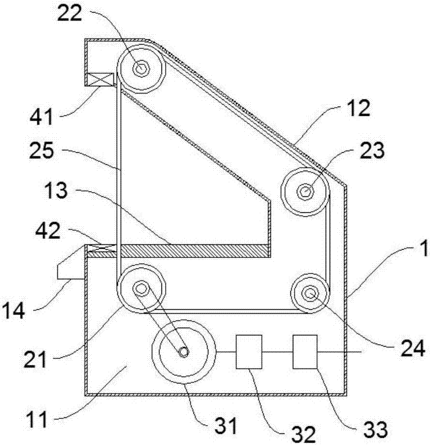
[0012] like figure 1 A belt sander shown includes a frame 1. The frame 1 includes a base 11 at the bottom and an inclined column 12 fixed to the upper side of the base 11. The bottom of the column 12 is fixed on the base 11. On one side of the surface, the top of the column 12 is inclined to the top of the other side of the upper surface of the base 11; the upper surface of the base 11 is provided with a worktable 13, and the driving pulley 21 and the tension pulley 24 are arranged in the inner cavity of the base 11. The first driven pulley 22 and the second driven pulley 23 are arranged in the inner cavity of the column 12, and the driving pulley 21, the first driven pulley 22, the second driven pulley 23 and the tension pulley 24 all pass through The abrasive belt 25 is connected, wherein the abrasive belt 25 passes through the worktable 13...


PUM


Abstract

The invention discloses a grinding belt machine, and belongs to the technical field of grinding equipment. An existing grinding belt machine runs at a high speed during grinding or idling, and unnecessary energy consumption is generated. A traditional grinding belt machine is improved, a light source and a light receiver arranged on the workbench top are used for sensing whether a workpiece needs to be machined or not; and then a controller and a frequency converter are used for changing the rotation speed of a motor, the grinding belt machine rotates at low speed during idling and then stops rotating, and the grinding belt machine rotates at a high speed during grinding; and due to fast acceleration of the motor, the grinding belt machine cannot interfere with normal work, and energy can be saved as well.

Description

technical field [0001] The invention belongs to the technical field of grinding equipment, in particular to an abrasive belt machine with automatic speed adjustment. Background technique [0002] A belt machine is a kind of grinding equipment, which uses a moving abrasive belt to grind workpieces. It is a widely used equipment. The existing abrasive belt machine runs at high speed when grinding the workpiece, but when the operator removes the workpiece, the abrasive belt machine still runs at high speed, which causes unnecessary waste of energy for the abrasive belt machine. Contents of the invention [0003] The technical problem to be solved by the invention is to improve the existing sand belt machine to make it more energy-saving. [0004] The technical solution adopted by the present invention is to provide a belt sander whose rotation speed changes according to whether there is a load or not. [0005] The technical scheme that the present invention takes is: [00...

Claims


Application Information

Patent Timeline
IPC IPC(8): B24B21/18B24B55/00B24B49/12
CPCB24B21/18B24B49/12B24B55/00
Inventor 胡平乐郜立新
Owner ANHUI CHIZHOU WEISS ELECTROMECHANICAL
Learn More