A free-spinning flagpole

A flagpole and free technology, applied in the field of freely rotating flagpoles, can solve the problems of easy broken ropes, unsightly fluttering flags, and unfitness, etc., to achieve the effect of prolonging the service life, avoiding the flag around the pole, and freely rotating the flag surface

Active Publication Date: 2019-08-20
济宁高新科达科技项目服务有限公司
View PDF12 Cites 0 Cited by
  • Summary
  • Abstract
  • Description
  • Claims
  • Application Information

AI Technical Summary

Problems solved by technology

[0002] When raising the flag on the traditional flagpole, two ropes are needed. If the flagpole is high, the two ropes are not easy to control the flag surface, and when the wind blows, the rope makes a lot of noise when it hits the flagpole. The wind will roll on the flagpole, not only does the flag flutter unsightly, but it is also easy to wind the flag and damage it
[0003] In the prior art, the invention of the rotating flagpole is realized by installing a slewing bearing under the base of the flagpole. As everyone knows, the bearing under the base of the flagpole needs to bear a large moment, and two large slewing bearings are required. The price of the bearing is high and it is inconvenient to install. , it is not suitable to use the base to install the bearing to solve the rotation problem

Method used


Image

  • A free-spinning flagpole
  • A free-spinning flagpole
  • A free-spinning flagpole

Examples


Embodiment Construction

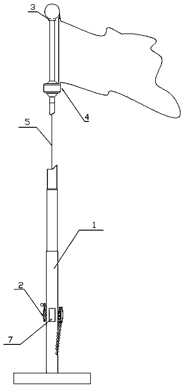
[0029] like Figure 1~Figure 8 As shown, a freely rotating flagpole of the present invention is mainly composed of a flagpole standpipe 1, a lifting mechanism 2, a rotary traction mechanism 3, a flag surface suspension 4 and a traction rope 5.

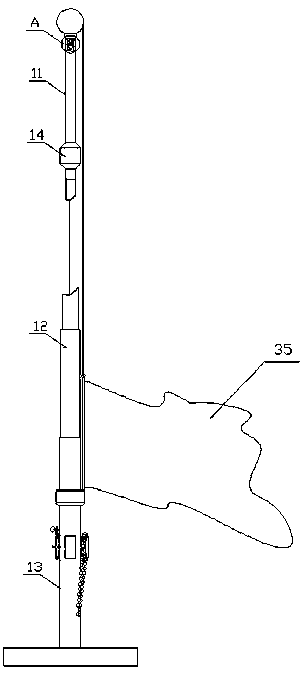
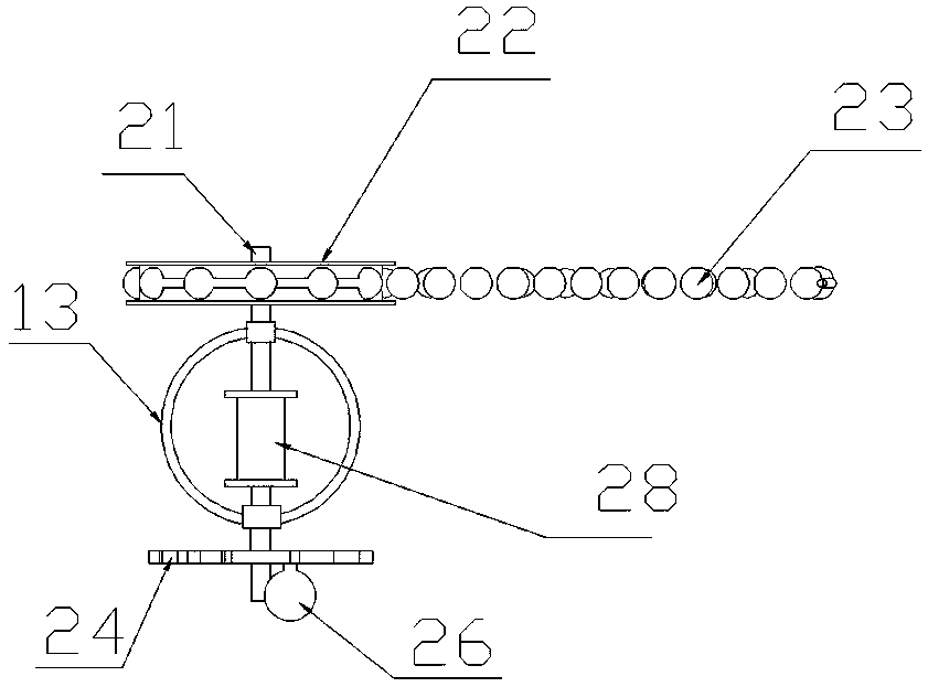
[0030] The flagpole standpipe 1 is a hollow tube structure, including a flagpole upper pipe 11, a flagpole middle part 12 and a flagpole lower pipe 13. The number depends on the total height of the flagpole standpipe 1. The lifting mechanism 2 is located on the lower tube 13 of the flagpole, and the rotary traction mechanism 3 is located on the top of the flagpole upper tube 11. The rotary traction mechanism 3 can be wound around the flagpole. The top of pipe 11 rotates, and the flag surface suspension 4 is positioned at the outer circumference of flagpole standpipe 1, and flag surface 35 is fixed on the described flag surface suspension 4, and one end of the traction rope 5 is fixed on the elevating mechanism 2, and the The other end...


PUM


Abstract

The invention discloses a free rotating flag post, and belongs to the technical field of small machinery. The technical problem needing to be solved is to provide the free rotating flag post, two ropes of the traditional flag post do not need to be pulled, a flag freely rotates with the wind and is not wound on the flag post because of the blowing wind; the technical scheme adopted for solving the technical problem is as follows: the free rotating flag post comprises a flag post standpipe, a lifting mechanism, a rotation hauling mechanism and a flag suspension and a hauling rope, the flag post standpipe comprises a flag post upper pipe, a flag post middle part and a flag post lower pipe, the rotation hauling mechanism rotates around the top end of the flag post upper pipe, the flag suspension is located at the outer periphery of the flat post standpipe, one end of the hauling rope is fixed on the lifting mechanism, the other end of the hauling rope penetrates through the interior of the flag post standpipe, enters the rotation hauling mechanism, gets out from the rotation hauling mechanism, and is connected on the flag suspension, the hauling rope is controlled through the lifting mechanism, then the flag suspension is lifted up and down along the outer part of the pipe wall of the flag post standpipe, and the flag suspension freely rotates on the excircle of the flag post standpipe through the rotation hauling mechanism.

Description

technical field [0001] The invention relates to a freely rotating flagpole, which belongs to the technical field of small machinery. Background technique [0002] When raising the flag on the traditional flagpole, two ropes are needed. If the flagpole is high, the two ropes are not easy to control the flag surface, and when the wind blows, the rope makes a lot of noise when it hits the flagpole. The wind will roll on the flagpole, not only does the flag flutter unsightly, but it is also easy to wind the flag and damage it. [0003] In the prior art, the invention of the rotating flagpole is realized by installing a slewing bearing under the base of the flagpole. As everyone knows, the bearing under the base of the flagpole needs to bear a large moment, and two large slewing bearings are required. The price of the bearing is high and it is inconvenient to install. , It is not suitable to use the base to install the bearing to solve the rotation problem. Contents of the inv...

Claims


Application Information

Patent Timeline
Patent Type & Authority Patents(China)
IPC IPC(8): E04H12/32
Inventor 曹进元
Owner 济宁高新科达科技项目服务有限公司
Why Eureka
Try Eureka