
Heading machine with drilling tool, scraper box, coring drilling rod and quartering hammer

A technology of roadheader and coring drill, which is used in earth-moving drilling, mining equipment, tunnels, etc., can solve the problems of time-consuming, labor-intensive, and difficult drilling, and achieve the effect of avoiding time-consuming and laborious, stable base, and huge power.

Inactive Publication Date: 2017-11-28
韩自俊
View PDF1 Cites 2 Cited by
  • Summary
  • Abstract
  • Description
  • Claims
  • Application Information

AI Technical Summary

Problems solved by technology

[0002] Today's roadheaders have excellent performance in coal roadway and soft rock, but when it comes to hard rock roadway, it is basically a theory, which is unrealistic. Drilling machines are only suitable for large-sized roadways and others. Drilling trucks and slag removal machines are used together, and small-sized roadways cannot be staggered. , it is necessary to widen the section that is not necessary, but it is time-consuming and laborious to stagger; the crust is composed of countless folds and lithology with different soft and hard rocks, and soft and hard rocks will frequently appear alternately. It can easily and quickly excavate. Real mines urgently need such a machine. Geological exploration units are in some areas where vegetation is particularly developed and the landform and geographical environment are particularly harsh. A low-cost and high-speed roadheader is needed; this invention is a technical supplement to the cutting head, telescopic structure and accompanying drilling tools of the patent No. ZL201621074091.4 roadheader with rake teeth, which improves the degree of automation and smooth blasting effect

Method used


Image

  • Heading machine with drilling tool, scraper box, coring drilling rod and quartering hammer
  • Heading machine with drilling tool, scraper box, coring drilling rod and quartering hammer
  • Heading machine with drilling tool, scraper box, coring drilling rod and quartering hammer

Examples


Embodiment Construction

[0032] The present invention will be further described below in conjunction with the accompanying drawings and examples.

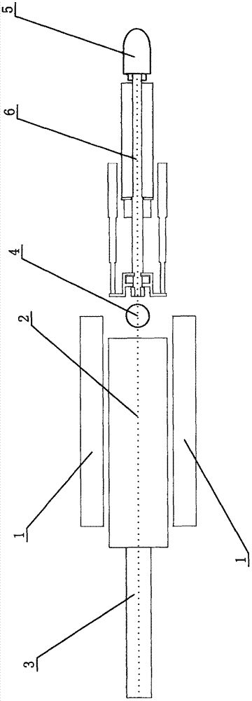
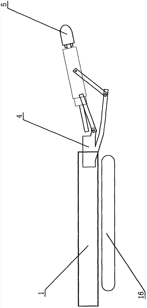
[0033]In the above-mentioned accompanying drawings: the structure of the first embodiment when the present invention is used is shown; Referring to the accompanying drawings, its basic structure is: the roadheader with drilling tool, scraper bucket, coring drill, breaker is an existing The roadheader is reformed from a roadheader, and its feature is: move the hydraulic motors, hydraulic pumps, cooling boxes, transformers, etc. Two single-arm drills 1 are side by side, the fixed seat 17 of the single-arm drill 1, that is, the maximum width of the single-arm drill 1 is less than 0.4 meters, the width of the scraper groove 3 of the roadheader is about 0.9 meters, and the two single-arm drills 1 plus the scraper groove 3 , that is, the total width of the machine is less than 2 meters, and the length is about 16 meters, which is slightly shorter than the existi...


PUM


Abstract

The invention relates to a roadheader equipped with a drilling tool, a rake tooth, a coring drill rod and a breaking hammer, which belongs to the category of mining equipment. It is restructured from an existing roadheader. Its features are: it solves the problems that the original cutting arm does not stretch or stretches, or the pressure bearing surface is too small when stretching and stretches, and the problem of hard rock tunneling cannot be solved. The power is driven by a hydraulic motor. The outer spray is changed to the inner water spray structure, so that the pick can be effectively cooled, and the longitudinal thrust is directly pushed and pulled by two hydraulic cylinders. Function, the cutting head is equipped with a detachable coring drill pipe and a small breaker, which can also be used as a roadway drill and a breaker, and there are 2 additional drilling tools on both sides, using the existing idle power to exchange , to achieve high-speed blasting holes. It is a new generation small tunnel boring machine that integrates the functions of drilling truck, slag removal machine, roadway drilling machine and roadheading machine. It can really drill soft and hard rocks. It has low cost and high speed Fast, light and flexible body.

Description

(1) Technical field [0001] The invention relates to a roadheader with a drilling tool, a scraper bucket, a coring drill rod and a breaker, in particular to a roadheader for tunneling in a mine, which belongs to the category of mining equipment. (2) Background technology [0002] Today's roadheaders have excellent performance in coal roadway and soft rock tunneling, but when it comes to hard rock tunneling, it is basically a theory, which is unrealistic. Drilling machines are only suitable for large-sized roadways and others. Drilling trucks and slag removal machines are used together, and small-sized roadways cannot be staggered. , had to widen the section that was not necessary, but it was time-consuming and laborious to stagger; the crust is composed of countless folds and lithology with different soft and hard rocks, and soft and hard rocks will frequently appear alternately. It can easily and quickly excavate. Real mines urgently need such a machine. Geological explorati...

Claims


Application Information

Patent Timeline
Patent Type & Authority Applications(China)
IPC IPC(8): E21D9/10E21D9/12
CPCE21D9/10E21D9/1006E21D9/106E21D9/1093E21D9/12
Inventor 韩自俊
Owner 韩自俊
Learn More