Welded structure

A welding structure and fillet welding technology, which is applied in welding equipment, ship construction, manufacturing tools, etc., can solve the problems of inability to apply welding structures, huge labor force, etc.

Active Publication Date: 2017-11-28
JFE STEEL CORP +1
View PDF9 Cites 1 Cited by
  • Summary
  • Abstract
  • Description
  • Claims
  • Application Information

AI Technical Summary

Problems solved by technology

[0008] However, in addition to the fact that many ships built by applying welding equivalent to the welding used in Non-Patent Document 1 to steel plates with a plate thickness of less than 50 mm did not cause any problems and sailed many times, based on steel plates with good toughness Based on the recognition that the parent material (shipbuilding grade E steel, etc.) sufficiently maintains the ability to stop brittle cracks, the brittle crack propagation stop characteristics of welded parts of shipbuilding steel materials are not specifically required in ship classification standards, etc.
[0033] However, in each of the techniques described in Patent Documents 3 to 5, it is necessary to limit the length of the fillet (or the width of the welded deposit) to 16 mm or less. Therefore, from the viewpoint of securing the strength of the fillet weld, it can be applied to joined parts ( Web) and the thickness of the joined parts (flange) is only 80mm at most
[0034] In addition, even if the plate thickness of the joining member (web) and the member to be joined (flange) is less than 80mm, considering the variation in the length of the fillet during actual construction, it is necessary to ensure the strength of the fillet weld. Ensuring the desired fillet length and limiting the fillet length to 16 mm or less in order to ensure brittle crack prevention performance also requires a huge amount of labor in terms of construction management
[0036] However, as described above, in each of the technologies described in Patent Documents 3 to 5, the plate thickness applicable to the joining member (web) and the member to be joined (flange) is only 80 mm at most, and thus cannot be applied to Welded structures with component thickness exceeding 80mm

Method used


Image

  • Welded structure
  • Welded structure
  • Welded structure

Examples


Embodiment

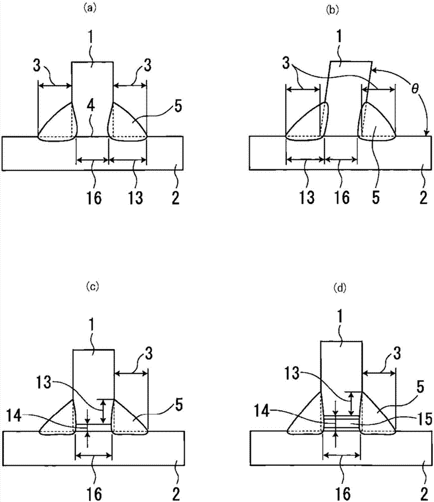
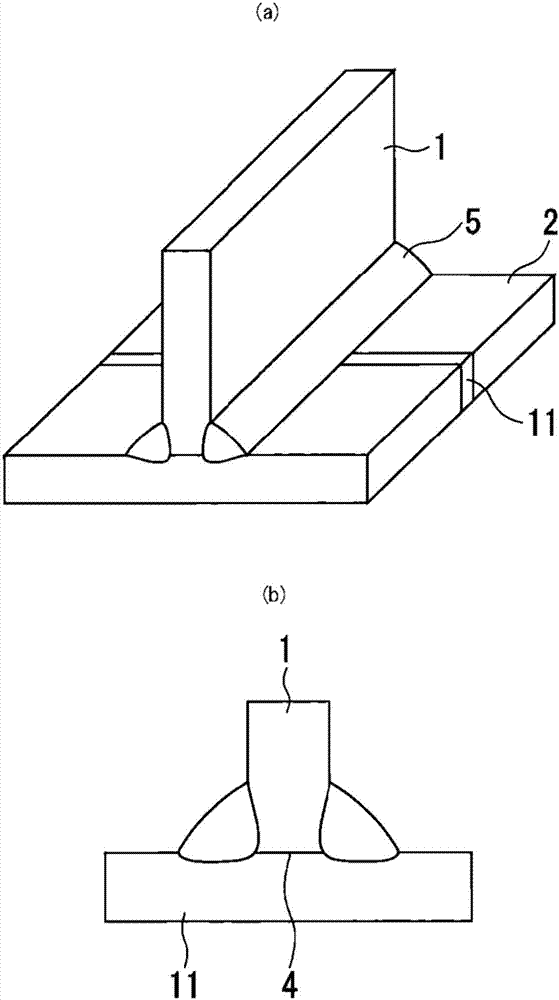
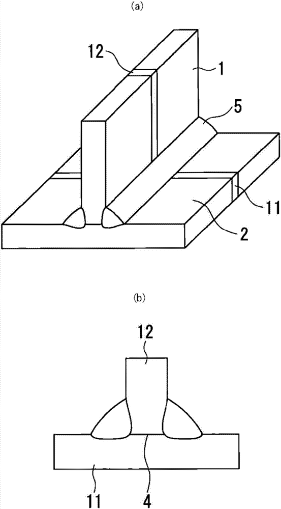
[0109] A thick steel plate with a thickness tw shown in Table 1 was used as a joining member (web plate), and a thick steel plate with a thickness tf shown in Table 1 was used as a member to be joined (flange), and they were fillet welded to produce out to become Figure 4 (a), (b), (c) shown in the shape of the actual structural size of the large fillet welded joint 9. Furthermore, in the fabricated large fillet welded joint 9, the figure 1 The unwelded portion 4 shown in (a), (c) or (d) is changed by changing the ratio Y of the unwelded portion (=(width B of the unwelded portion / joint member (web) thickness tw ) exists in the butt surface of the joining member 1 and the joined member 2. In addition, the joined member (flange) is formed into a thick steel plate (only the base material) ( Figure 4 (a) in) or thick steel plates with butt welded joints ( Figure 4 In (b), (c)), the joined part (web) is formed into a thick steel plate (base metal only) ( Figure 4 (a), (b)) or ...


PUM

PropertyMeasurementUnit
thicknessaaaaaaaaaa

Abstract

This welded structure comprises a fillet welded joint which joins a joining member (1) and a joined member (2) having a plate-thickness of 50 mm or larger, in which an end face of the joining member (1) is in contact with a surface of the joined member (2). The weld leg length (3) and the welding width (13) of the fillet welded joint are each larger than 16 mm. A surface of the fillet welded joint at which the end face of the joining member (1) is in contact with the surface of the joined member (2) includes a non-welded part (4) at which the cross section of the fillet welded joint is not smaller than 95% of the plate-thickness (tw) of the joining member (1). Further, regarding a fillet welded metal (5) of the fillet welded joint, a predetermined relationship is satisfied between the Charpy impact test fracture transition temperature (vTrs (DEG C)) of the fillet welded metal (5) and the plate-thickness (tf) of the joined member (2), or among the temperature (vTrs (DEG C)), the thickness (tf), and a value (L) which is the lower between the weld leg length (3) and the welding width (13).

Description

technical field [0001] The present invention relates to, for example, a welded steel structure (welded structure) in which thick steel plates are used for welding construction, such as a large container ship and a bulk carrier. In particular, the present invention relates to a welded structure excellent in brittle crack propagation stopping properties capable of stopping the propagation of brittle cracks generated from a base material of a thick steel plate or a welded joint before reaching large-scale failure of the structure. Background technique [0002] Unlike tankers and the like, container ships and bulk carriers have a structure in which the opening of the upper part of the ship is enlarged in order to improve loading capacity, cargo handling efficiency, and the like. Therefore, in container ships and bulk carriers, it is particularly necessary to increase the strength or thicken the hull plating. [0003] In addition, container ships tend to be enlarged in recent ye...

Claims


Application Information

Patent Timeline
Patent Type & Authority Applications(China)
IPC IPC(8): B23K9/02B23K9/00B63B9/06B23K31/00
CPCB23K9/00B23K9/02B23K31/00B63B73/43B23K9/025B23K9/16B23K31/02
Inventor 半田恒久伊木聪大井健次丰田昌信木治升渡边盛太
Owner JFE STEEL CORP
Why Eureka
Try Eureka