Winding machine

A winding machine and roll forming technology, which is applied in the direction of thin material processing, conveying filamentous materials, transportation and packaging, etc., can solve the problems of not being able to choose freely, and achieve the effect of highly effective damping effect

Active Publication Date: 2020-08-18
OERLIKON TEXTILE GMBH & CO KG
View PDF6 Cites 0 Cited by
  • Summary
  • Abstract
  • Description
  • Claims
  • Application Information

AI Technical Summary

Problems solved by technology

However, the diameter of the chuck is predetermined by the winding tube and cannot be freely selected

Method used


Image

  • Winding machine
  • Winding machine
  • Winding machine

Examples


Embodiment Construction

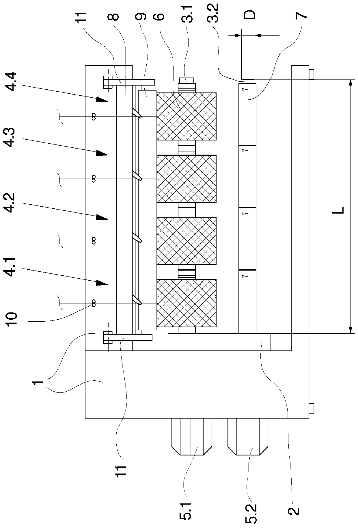
[0027] An exemplary embodiment of a winder according to the invention is in figure 1 is schematically shown in . The winding machine has two substantially protruding winding spindles 3.1 and 3.2 which are arranged on a winding tower 2 which is mounted so that it can be mounted on the machine frame 1 Rotate. Four winding stations 4.1 to 4.4 extend along the winding spindles 3.1 and 3.2, in which four bobbins 6 are wound in parallel. For this, the winding spindles 3.1 and 3.2 are each coupled to one spindle motor 5.1 and 5.2.

[0028] The number of winding stations is exemplary. In principle, a winder of this type has several winding stations in order to wind several bobbins simultaneously.

[0029] The winding stations 4.1 to 4.4 are assigned to the contact pressure roller 9 and the traversing device 8, wherein the traversing device 8 for each winding station 4.1 to 4.4 has a thread guiding in each case in a reciprocating manner. guide wire device. The contact pressure ro...


PUM


Abstract

The invention relates to a winding machine for winding groups of wires to form bobbins. For this purpose, the winding machine has winding spindles (3.1, 3.2) with protruding clamping chucks (12) for receiving a plurality of bobbin tubes (7), which can Driven by a multi-part drive shaft (16) mounted in a hollow support (20). The rear bearing shaft (16.2) is coupled to the driver, the front bearing shaft (16.1) connected to the rear bearing shaft is coupled to the clamping chuck and is mounted in the hollow support by damping bearings (25.1, 25.2). In order to allow strong damping without structurally weakening the clamping chuck, additional damping means are provided between the front bearing shaft and the hollow support, which are arranged in an axially offset manner on the outside of the bearing.

Description

technical field [0001] The invention relates to a winding machine for winding groups of wires to form bobbins. Background technique [0002] In the production of synthetic yarns in the melt spinning process, the yarns of one spinning station are wound together in parallel to form bobbins. For this, known winding machines are used, which in each case have one winding station per thread, wherein the winding stations run in parallel along the winding spindles. The winding spindle is arranged to protrude on the spindle support so that the bobbin wound on the circumference of the winding spindle when finished can be removed from the free end. It is now desirable to produce as many threads as possible in one spinning station, so that many bobbins have to be wound in parallel in a winding machine, and particularly elongated protruding winding spindles are required. [0003] However, the basic design of this type of winding spindle takes into account very high thread speeds during...

Claims


Application Information

Patent Timeline
Patent Type & Authority Patents(China)
IPC IPC(8): B65H54/547
CPCB65H54/547B65H2701/3132B65H2601/524
Inventor H·瓦尔特曼K·谢弗
Owner OERLIKON TEXTILE GMBH & CO KG
Why Eureka
Try Eureka