Supercharge Your Innovation With Domain-Expert AI Agents!

Thermostatic device for controlling the circulation of a fluid, and thermostatic valve including such a device

A thermostatic device, a technology for controlling fluids, applied in valve operation/release device, valve device, temperature control, etc., to solve problems such as leakage at seals

Active Publication Date: 2017-11-28
VERNET SA
View PDF10 Cites 1 Cited by
  • Summary
  • Abstract
  • Description
  • Claims
  • Application Information

AI Technical Summary

Problems solved by technology

This solution has a limited mechanical strength for high fluid pressures and over long periods, with the risk of leakage at the closure

Method used


Image

  • Thermostatic device for controlling the circulation of a fluid, and thermostatic valve including such a device
  • Thermostatic device for controlling the circulation of a fluid, and thermostatic valve including such a device
  • Thermostatic device for controlling the circulation of a fluid, and thermostatic valve including such a device

Examples


Embodiment Construction

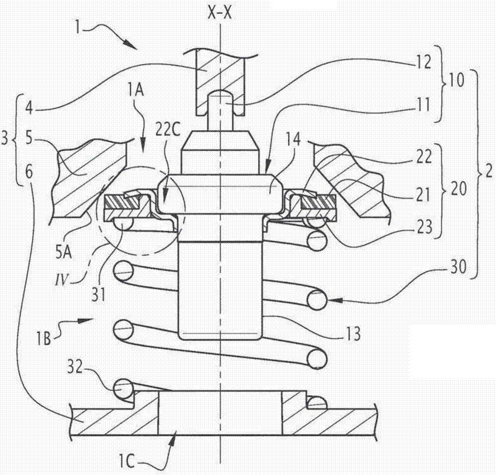
[0018] Figure 1 to Figure 4 A valve 1 is shown comprising a thermostat 2 for regulating the flow of fluid. This fluid is for example a cooling fluid, the valve 1 belonging in particular to the cooling circuit of a heat engine, in particular a motor vehicle engine, however as described in the technical field section of this document, this example is not limiting.

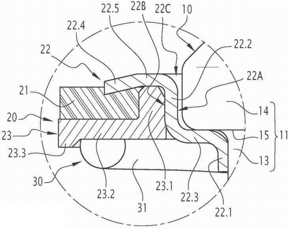
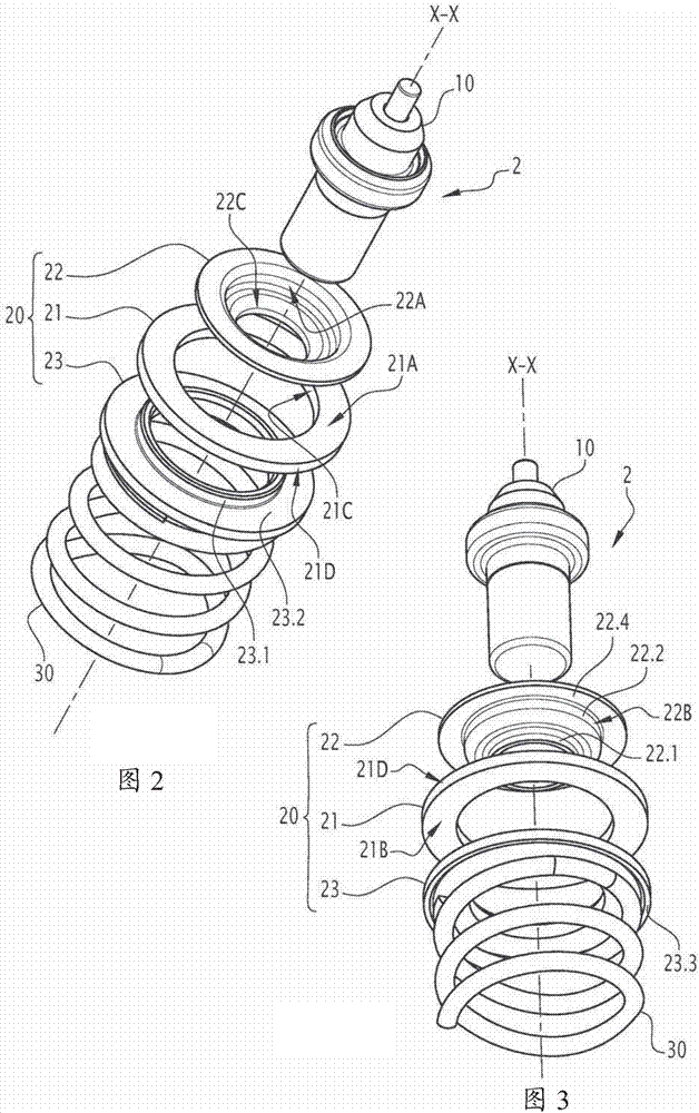
[0019] figure 2 with image 3 Only the thermostat 2 is shown in the figure 1 , the device 2 is arranged in parts 4, 5 and 6 of the housing 3 of the valve 1, please note that in the valve 1 such as figure 1 These parts 4, 5 and 6 are fixed relative to each other in use as shown in , for example integrated into each other and / or fixedly fastened to each other. In practice, in figure 1 In , parts 4, 5 and 6 of housing 3 are only partially and schematically shown, their embodiments being non-limitative with respect to the invention. In all cases, when the valve 1 is in the use configuration, the housing 3 conveys...


PUM


Abstract

The invention relates to a thermostatic device which includes a thermostatic element and a stopper, which is axially movable relative to a stationary seat of a housing so as to open and close a passage for the circulation of fluid and which is connected to a movable portion of the thermostatic element such that, during the expansion of a thermoexpansible material of the thermostatic element, the movable portion drives the stopper axially relative to the seat. The stopper includes a seal, which rests tightly against the seat when the fluid circulation passage is closed by the stopper, a first part, which is provided with an inner bore for receiving the movable portion of the thermostatic element, and a second part which is separate from the first part, the seal being axially clamped between the first and second parts. In order for the integration of the seal in the stopper to be both economical and efficient, the invention provides for the first and second parts of the stopper to be made of metal, for the second part to be mounted around the first part, for the part facing the axis of the second part to form a peripheral edge for attaching said second part to the outer surface of the first part, and for the first part to form an axial abutment for the edge of the second part, so as to position the first and second parts axially relative to one another by applying a predetermined clamping load to the seal.

Description

technical field [0001] The invention relates to a thermostatic device, and a thermostatic valve comprising such a device. [0002] The invention relates in particular to a thermostat and a valve for use in the cooling circuit of thermal engines, in particular those of motor vehicles, heavy trucks, two-wheeled vehicles and stationary engines. That is, the scope of application is not limited to the present invention, since the device and valve according to the present invention can be used in various other fluid circuits, such as gearbox cooling circuits, water circuits, oil circuits and the like. Background technique [0003] In many applications in the field of fluids, especially for cooling vehicle heat engines, thermostatic valves are used to regulate the flow of a fluid based on the temperature of the fluid, ie to distribute the incoming fluid in different flow paths. These valves are called thermostatic because the movement of their internal closure relative to the valv...

Claims


Application Information

Patent Timeline
Patent Type & Authority Applications(China)
IPC IPC(8): F16K31/64
CPCF16K31/002F16K1/46G05D23/022F01P7/16F16K1/465
Inventor 威廉·达西尔瓦L·马博克斯
Owner VERNET SA
Features
  • R&D
  • Intellectual Property
  • Life Sciences
  • Materials
  • Tech Scout
  • Unparalleled Data Quality
  • Higher Quality Content
  • 60% Fewer Hallucinations
Learn More