Liquid separation equipment

A technology of liquid separation and equipment, applied in the field of separation, can solve problems such as poor separation effect, and achieve the effect of simple structure, good separation effect and convenient use

Inactive Publication Date: 2017-12-01
潘幸迪
View PDF0 Cites 0 Cited by
  • Summary
  • Abstract
  • Description
  • Claims
  • Application Information

AI Technical Summary

Problems solved by technology

[0003] The object of the present invention is to provide a liquid se

Method used


Image

  • Liquid separation equipment
  • Liquid separation equipment
  • Liquid separation equipment

Examples


Embodiment 1

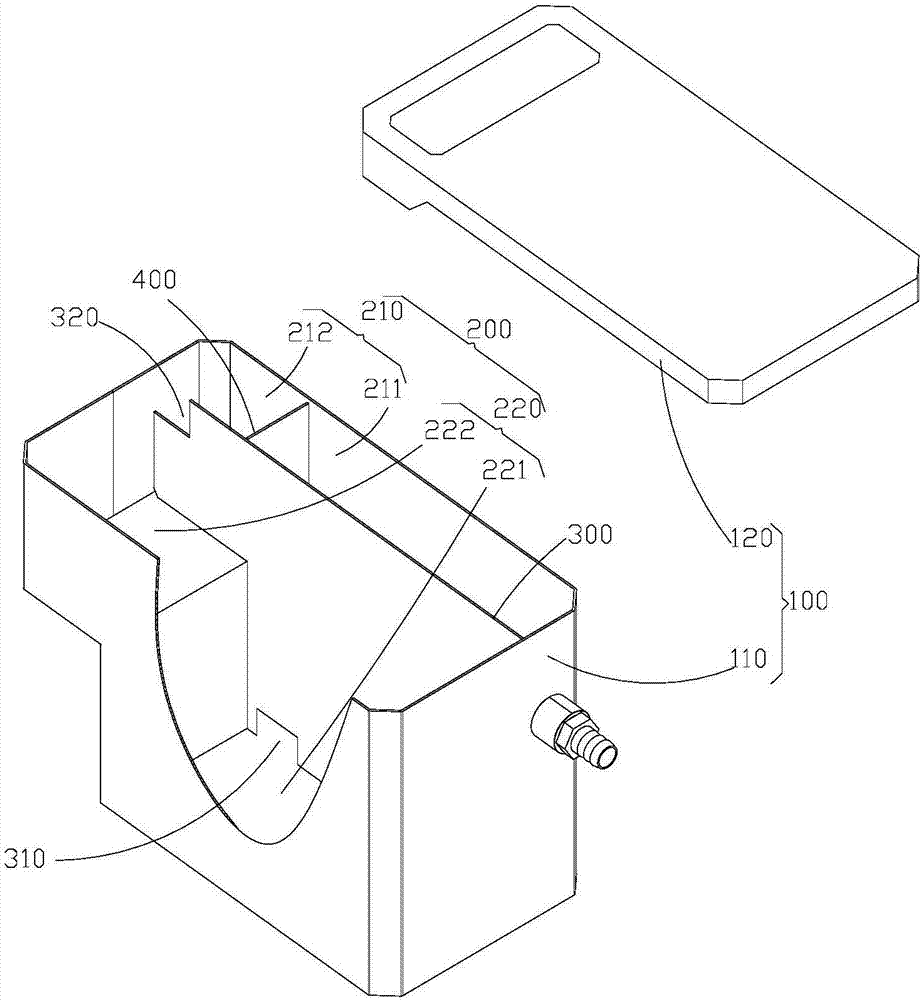
[0031] The present invention provides a liquid separation device, including a liquid separation box 100 , through a reasonable layout of each chamber inside the liquid separation box 100 , to achieve the purpose of improving the liquid separation effect.

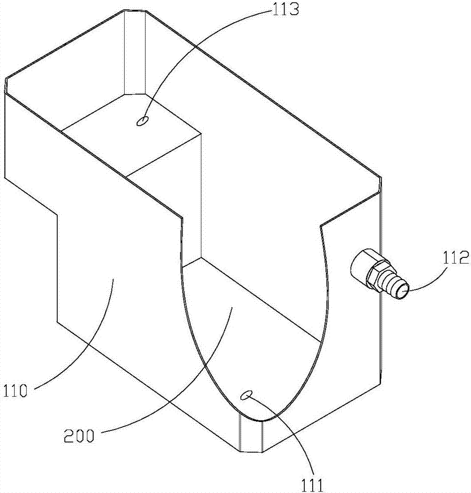
[0032] Such as figure 1 As shown, the liquid separation box 100 includes a box body 110 and a box cover 120 , the box body 110 forms a liquid containing chamber 200 with an open upper end, and the box body 110 can be sealed after the box cover 120 is closed on the box body 110 .

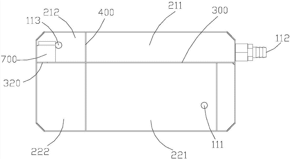
[0033] The liquid-holding chamber 200 is provided with a transverse partition 300, and the upper edge of the transverse partition 300 is flush with the upper edge of the box body 110. The transverse partition 300 divides the liquid-containing chamber 200 into two chambers, and the two chambers are located at The first liquid chamber 210 at the rear side and the second liquid chamber 220 at the front side. The first liquid containing chamber 210 is...

Embodiment 2

[0042] The liquid separation equipment provided by the embodiment of the present invention has the same realization principle and technical effect as the foregoing method embodiment. For the sake of brief description, for the parts not mentioned in the device embodiment, please refer to the corresponding method in the foregoing method embodiment. content.

[0043] In the above-mentioned embodiment, in order to ensure that the actions of discharging the second liquid and the first liquid are carried out at the same time, the height of the second liquid outlet 320 and the height of the first liquid outlet hole 112 should have a certain correlation, that is, when the liquid separation box 100 is horizontal When placed, the second liquid outlet 320 and the first liquid outlet 112 should be located at the same height. Therefore, the liquid separation box 100 needs to be leveled before use to avoid a height difference between the second liquid outlet 320 and the first liquid outlet ...

Embodiment 3

[0051] The difference between this embodiment and embodiment 2 is that, as Figure 6 As shown, the liquid separation chamber 221 is provided with a liquid separator 2213 arranged longitudinally, and the height of the liquid separator 2213 is flush with the bottom wall of the left half of the liquid separation box 100 . The liquid separator 2213 divides the liquid separation chamber 221 into a dynamic chamber 2212 and a static chamber 2211 , the dynamic chamber 2212 is farther away from the liquid floating chamber 222 than the static chamber 2211 , and the liquid inlet hole 111 communicates with the dynamic chamber 2212 .

[0052] Such as Figure 7 As shown, the liquid separator 2213 is a rectangular structure, and two liquid outlets 2214 are provided at the bottom thereof. The dynamic cavity 2212 communicates with the static cavity 2211 through the liquid outlet 2214 . The waste liquid to be separated enters the dynamic chamber 2212 through the liquid inlet hole 111, and the...


PUM


Abstract

The invention discloses a liquid separation device, which comprises a liquid separation box, and a liquid containing cavity is arranged inside the liquid separation box. A transverse partition is arranged in the liquid-holding chamber to form a first liquid-holding chamber and a second liquid-holding chamber. A vertical partition is arranged in the first liquid containing chamber to form a clean liquid chamber and a waste liquid chamber. The second liquid containing chamber includes a liquid separation chamber and a liquid floating chamber, and the bottom of the liquid floating chamber is higher than the bottom of the liquid separation chamber. The bottom of the horizontal partition is provided with a first liquid outlet, and the top of the horizontal partition is provided with a second liquid outlet. The liquid separation chamber communicates with the clean liquid chamber through the first liquid outlet, and the liquid floating chamber communicates with the waste liquid chamber through the second liquid outlet. connected. The liquid separation box is provided with a liquid inlet hole, a first liquid outlet hole and a second liquid outlet hole. The liquid inlet hole communicates with the liquid separation chamber, the first liquid outlet hole communicates with the clean liquid chamber, and the second liquid outlet hole communicates with the waste liquid chamber. The cavities communicate. Since the bottom of the liquid floating chamber is higher than the bottom of the liquid separation chamber, the first liquid at the bottom of the liquid floating chamber will not be impacted by the first liquid in the liquid separation chamber, and the first liquid and the second liquid in the liquid floating chamber can achieve static separation , the separation effect is good.

Description

technical field [0001] The invention belongs to the technical field of separation, and in particular relates to a liquid separation device. Background technique [0002] At present, in the process of chemical production, such as in the field of petroleum processing, the separation of liquids in different phases is involved, especially liquids that are incompatible with each other and have different densities. The existing separation equipment has a relatively complicated structure, and the separation effect is still unsatisfactory. Contents of the invention [0003] The object of the present invention is to provide a liquid separation device to solve the above-mentioned problem of poor separation effect. [0004] To achieve the above object, the present invention provides the following technical solutions: [0005] A liquid separation device, comprising a liquid separation box, the liquid separation box is provided with a liquid containing cavity; [0006] A horizontal ...

Claims


Application Information

Patent Timeline
IPC IPC(8): B01D17/02B01D36/00B01D36/02
CPCB01D17/0214B01D36/006B01D36/02
Inventor 潘幸迪
Owner 潘幸迪
Why Eureka
Try Eureka