Feeding and discharge stock bin for grinding of bearing rings

A bearing ring and silo technology, applied in the direction of grinding feed motion, grinding machine parts, grinding/polishing equipment, etc., can solve the problems of easy dumping of finished products, difficulty in finishing, and high labor costs, so as to facilitate subsequent operations. Effect

Active Publication Date: 2017-12-01
常州市巨人机器人科技有限公司
View PDF9 Cites 3 Cited by
  • Summary
  • Abstract
  • Description
  • Claims
  • Application Information

AI Technical Summary

Problems solved by technology

[0003] For the storage of bearing ring blanks, there is no device in the traditional automatic production line that can centrally store multiple bearing ring blanks at the same time, and cooperate with the follow-up truss manipulator to carry out subsequent processing. The storage of bearing rings is very easy. Dumping, and if manual sorting is used, after sub-assembly, the truss manipulator is used again, not only the work efficiency is low, but the labor cost is high. The most important thing is that the workpiece after manual sorting is difficult to be grasped by the truss manipulator, which is not conducive to the operation of the production line. There are different types of bearing rings, and the storage and arrangement of bearing rings of different models and sizes is more complicated;
[0004] For the storage of finished bearing rings, the situation is even more complicated. If a truss manipulator is used to put the finished products into the storage box one by one, the finished products are easy to dump, and it is difficult to sort them out. After the grinding process is completed, the finished workpieces , is magnetic, if it cannot be effectively demagnetized, it will be very difficult to follow up;
[0005] Therefore, in the traditional automatic production line for groove grinding of bearing rings, there is no good special setting for storing bearing ring blanks and finished products

Method used


Image

  • Feeding and discharge stock bin for grinding of bearing rings
  • Feeding and discharge stock bin for grinding of bearing rings
  • Feeding and discharge stock bin for grinding of bearing rings

Examples


Embodiment Construction

[0028] The present invention is described in further detail below in conjunction with the embodiment that accompanying drawing provides.

[0029] One of the specific implementation methods, such as Figure 1~4 Shown:

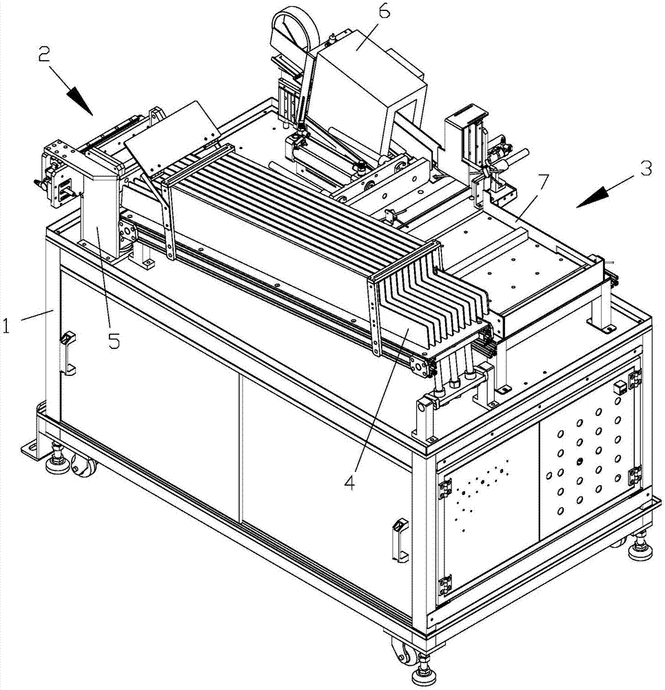
[0030] A bearing ring grinding loading and unloading material bin, including a frame 1, the two sides of the frame 1 are respectively provided with a rough material bin 2 and a finished product material bin 3, and the blank material bin 2 includes a feeding gravity feeder 4 and a feeding top Lifting mechanism 5, finished product bin 3 includes demagnetization mechanism 6 and finished product pushing mechanism 7, bearing ring channel grinding rough parts are put into rough material bin 2, bearing ring channel grinding finished parts are put into finished product bin 3, of which,

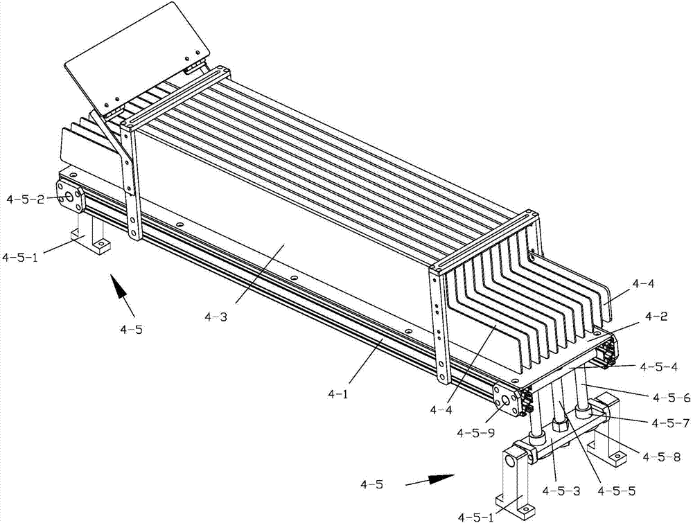
[0031] -The feeding gravity chute 4 includes 2 chute frames 4-1, the top of the 2 chute frames 4-1 has a slideway plate 4-2, and the slideway plate 4-2 is provided with a plurality of...


PUM


Abstract

The invention discloses a feeding and discharge stock bin for grinding of bearing rings. The feeding and discharge stock bin comprises a rack, and a blank stock bin and a finished product stock bin are separately arranged on the two sides on the rack; the blank stock bin comprises a feeding gravity material channel and a feeding jacking mechanism; the finished product stock bin comprises a demagnetization mechanism and a finished product pushing mechanism; bearing ring channel grinding processing blanks are put into the blank stock bin; and bearing ring channel grinding processing finished products are put into the finished product stock bin. According to the feeding and discharge stock bin, the structure is reasonable, manufacturing and maintenance cost is low, operation is simple, the bearing ring blanks and finished products can be stored, transported and arranged, automatic loading and unloading operation for workpieces is achieved through cooperation with an external truss mechanical hand, besides, the feeding and discharge stock bin is applicable to the bearing rings of different models, the bearing rings can be prevented from inclining, and the bearing ring finished products can be demagnetized.

Description

technical field [0001] The invention relates to a clamping device used in an automatic production line for groove grinding of bearing rings. Background technique [0002] In the automatic production line of bearing ring groove grinding in the factory workshop, a large number of completed blanks and finished products will continue to be produced, and how to store, transport and organize a large number of completed blanks and finished products is a relatively big problem; [0003] For the storage of bearing ring blanks, there is no device in the traditional automatic production line that can centrally store multiple bearing ring blanks at the same time, and cooperate with the follow-up truss manipulator to carry out subsequent processing. The storage of bearing rings is very easy. Dumping, and if manual sorting is used, after sub-assembly, the truss manipulator is used again, not only the work efficiency is low, but the labor cost is high. The most important thing is that the ...

Claims


Application Information

Patent Timeline
Patent Type & Authority Applications(China)
IPC IPC(8): B24B41/00
CPCB24B41/005Y02P70/10
Inventor 沈金伟陈冬明
Owner 常州市巨人机器人科技有限公司
Why Eureka
Try Eureka