A permanent magnetic repulsion type magnetic levitation linear guide

A linear guide, magnetic levitation technology, applied in the direction of holding devices, magnetic bearings, bearings, etc. with magnetic attraction or thrust, can solve the problems of non-adjustable bearing stiffness, complex structure and control, low stability, etc., to achieve good adaptability, Adjustable bearing stiffness and good stability

Active Publication Date: 2019-06-11
KUNMING UNIV OF SCI & TECH
View PDF5 Cites 0 Cited by
  • Summary
  • Abstract
  • Description
  • Claims
  • Application Information

AI Technical Summary

Problems solved by technology

[0004] The technical problem to be solved by the present invention is: the present invention provides a permanent magnetic repulsion type magnetic levitation linear guide, which is used to solve the current problems of the current magnetic levitation linear guide, such as low stability, poor suspension balance controllability, complex structure and control, and load-bearing rigidity. Problems of non-adjustability and poor adaptability

Method used


Image

  • A permanent magnetic repulsion type magnetic levitation linear guide
  • A permanent magnetic repulsion type magnetic levitation linear guide
  • A permanent magnetic repulsion type magnetic levitation linear guide

Examples


Embodiment 1

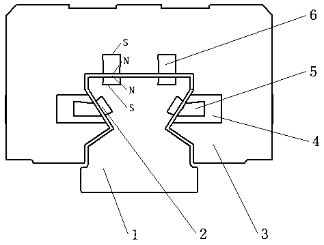
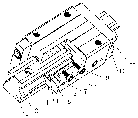
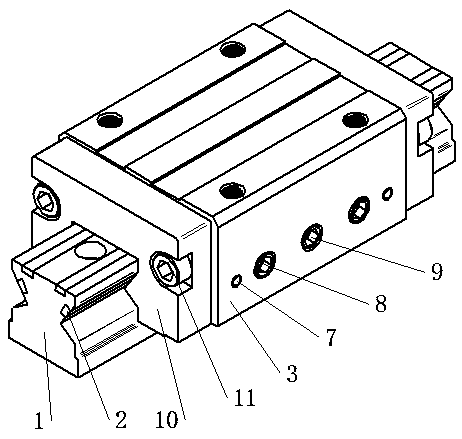
[0040] Embodiment 1: as Figure 1-20 As shown, a permanent magnetic repulsion type magnetic levitation linear guideway includes a guide rail 1, a guide rail magnetic strip 2, a slider body 3, an adjustment block 4, a side slider body magnetic strip 5, an upper slider body magnetic strip 6, and a guide pin 7. Adjusting screw 8, locking screw 9, side plate 10, side plate screw 11.

[0041] Further, the guide rail 1 includes four guide rail grooves 12, two are distributed on the top surface and two are distributed on the inclined side, and each guide rail groove 12 includes a guide rail groove bottom surface 13 and a guide rail groove inclined side surface 14; Described guide rail magnetic strip 2 comprises guide rail magnetic strip bottom surface 15, guide rail magnetic strip oblique side 16 and guide rail magnetic strip top surface 17, and described guide rail magnetic strip 2 is a permanent magnet, wherein: guide rail magnetic strip bottom surface 15 is S pole magnetic, guide ...

Embodiment 2

[0046] Embodiment 2: The structure of this embodiment is the same as that of Embodiment 1, the difference is that the magnetic strip 2 of the guide rail, the magnetic strip 5 of the side slider body and the magnetic strip 6 of the upper slider body can be composed of multiple small magnetic strips, so as to avoid the difficulty and ease of processing and manufacturing. The problem of breaking, the length of the guide rail 1 can be determined according to actual requirements.


PUM


Abstract

The invention relates to a permanent magnet repulsion type magnetic suspension linear guide rail and belongs to the technical field of transmission engineering components. The permanent magnet repulsion type magnetic suspension linear guide rail comprises a guide rail, guide rail magnetic strips, a sliding block body, an adjusting block, a lateral sliding body magnetic stripe, an upper sliding block body magnetic stripe, guide pin shafts, an adjusting screw, a locking screw, side plates and side plate screws. According to the permanent magnet repulsion type magnetic suspension linear guide rail, the four pairs of permanent magnet repulsion type magnetic suspension magnet set magnetic strips are correspondingly mounted on the guide rail and the sliding block body, the repulsion acting directions of two pairs of magnetic suspension magnet sets are the up-down directions, the repulsion acting directions of the two pairs of magnetic suspension magnet sets are the left-right internally-inclined directions, and the stable repulsion magnetic suspension structure is formed; and gaps between the magnetic strips of the two pairs of magnetic suspension magnet sets on the two inclined side faces can be adjusted. According to the permanent magnet repulsion type magnetic suspension linear guide rail, the guide rail is in non-mechanical contact with the sliding block body by the adoption of the permanent magnet repulsion magnetic suspension, and the guide rail has the beneficial effects of being free of mechanical wear and free of lubricating and can be applied to a precision machine. The guide rail has the beneficial effects of being good in repulsion suspension stability, high in antijamming capability, adjustable in bearing rigidity, good in applicability, compact and simple in structure and easy to apply and popularize.

Description

technical field [0001] The invention relates to a permanent magnetic repulsion type magnetic levitation linear guide rail, which belongs to the technical field of transmission engineering components. Background technique [0002] The function of the linear guide is to support and guide the moving parts to perform reciprocating linear motion in a given direction. Usually, the linear guide is required to bear a certain torque and maintain high linear motion accuracy under high load conditions. Linear guides are divided into sliding friction guides, rolling friction guides, elastic friction guides, fluid friction guides, etc., and are mainly used in automatic machinery such as CNC machine tools. Common linear guides, whether it is sliding friction or rolling friction There is mechanical contact between the relative moving surfaces, and friction is unavoidable. The friction of the linear guide rail not only leads to the consumption of transmission power but also affects the guid...

Claims


Application Information

Patent Timeline
Patent Type & Authority Patents(China)
IPC IPC(8): F16C32/04H02N15/00
CPCF16C32/0406H02N15/00
Inventor 樊瑜瑾何伟李浙昆
Owner KUNMING UNIV OF SCI & TECH
Why Eureka
Try Eureka