Multistage steam jet vacuum-pumping system with double backpressure steam condensers

A vacuum system and condenser technology, applied in steam/steam condensers, lighting and heating equipment, etc., can solve the problems of accident expansion, decrease of extraction capacity, increase of extraction volume, etc., to reduce coal consumption for power generation, without Effects of mechanical wear and stable output

Active Publication Date: 2014-07-23
普瑞森能源科技(北京)股份有限公司
View PDF5 Cites 12 Cited by
  • Summary
  • Abstract
  • Description
  • Claims
  • Application Information

AI Technical Summary

Problems solved by technology

Due to the pressure difference of the condenser, the steam extraction volume of the steam extraction pipeline of the high pressure condenser 201 must be increased, the steam extraction volume of the steam extraction pipeline of the low pressure condenser 101 is limited, and the resistance of the two steam extraction pipelines reaches Therefore, under the condition of good vacuum tightness, the pressures of the high-pressure condenser 201 and the low-pressure condenser 101 will be basically the same, and the pressure will be close to the pressure of the high-pressure condenser 201, which cannot realize the ideal dual back pressure operation
To solve this problem, figure 2 It shows another double back pressure design scheme in the prior art, in which part of the unit connects the air extraction pipelines 301, 401 of the high pressure condenser 201 and the low pressure condenser 101 to the vacuum pump 801 respectively, so that although the double back pressure of the unit is realized However, there are the following three problems: 1. The safety of unit operation is reduced. Generally, units above 600MW are equipped with three vacuum pumps, 1-2 vacuum pumps are running, and the rest are standby. When one vacuum pump is connected to one condenser , when the vacuum pump fails, there is no backup pump, which will easily cause the accident to expand; 2. The economy of the unit cannot maintain the best state. When the circulating water temperature is low, the low-pressure condenser will exceed the ultimate vacuum, and the high-pressure condenser vacuum will be low , so that neither side can operate under optimal vacuum
3. The load distribution between the vacuum pumps is not flexible. One vacuum pump corresponds to one condenser. When the output of the vacuum pump drops or the vacuum tightness of the condenser on one side is poor, the load cannot be transferred to other vacuum pumps, which will also cause increase in condenser pressure
[0005] 1. The water ring vacuum pump uses water as the working fluid. The temperature of the working fluid is controlled by the cooling water (circulating water or starting water). The temperature of the cooling water is affected by the climatic conditions, and the temperature changes greatly. Especially in summer, the temperature of the circulating water may reach More than 30 degrees, plus a certain heat transfer temperature difference, the temperature of the working fluid may reach more than 40 degrees. Under vacuum, a large amount of vaporization of the working fluid will cause cavitation and high noise of the vacuum pump, and the pumping capacity will decrease, making it impossible to maintain condensation. The minimum vacuum of the device seriously affects the economical and safe operation of the unit
[0006] 2. The power consumption of the water ring vacuum pump is high, and two water ring vacuum pumps need to be operated normally
[0007] 3. The water ring vacuum pump is a dynamic device, and the maintenance of the equipment is relatively large

Method used


Image

  • Multistage steam jet vacuum-pumping system with double backpressure steam condensers
  • Multistage steam jet vacuum-pumping system with double backpressure steam condensers
  • Multistage steam jet vacuum-pumping system with double backpressure steam condensers

Examples


Embodiment Construction

[0099] In the following, specific implementation manners will be explained with reference to the concept of the present invention in conjunction with the accompanying drawings of the present application.

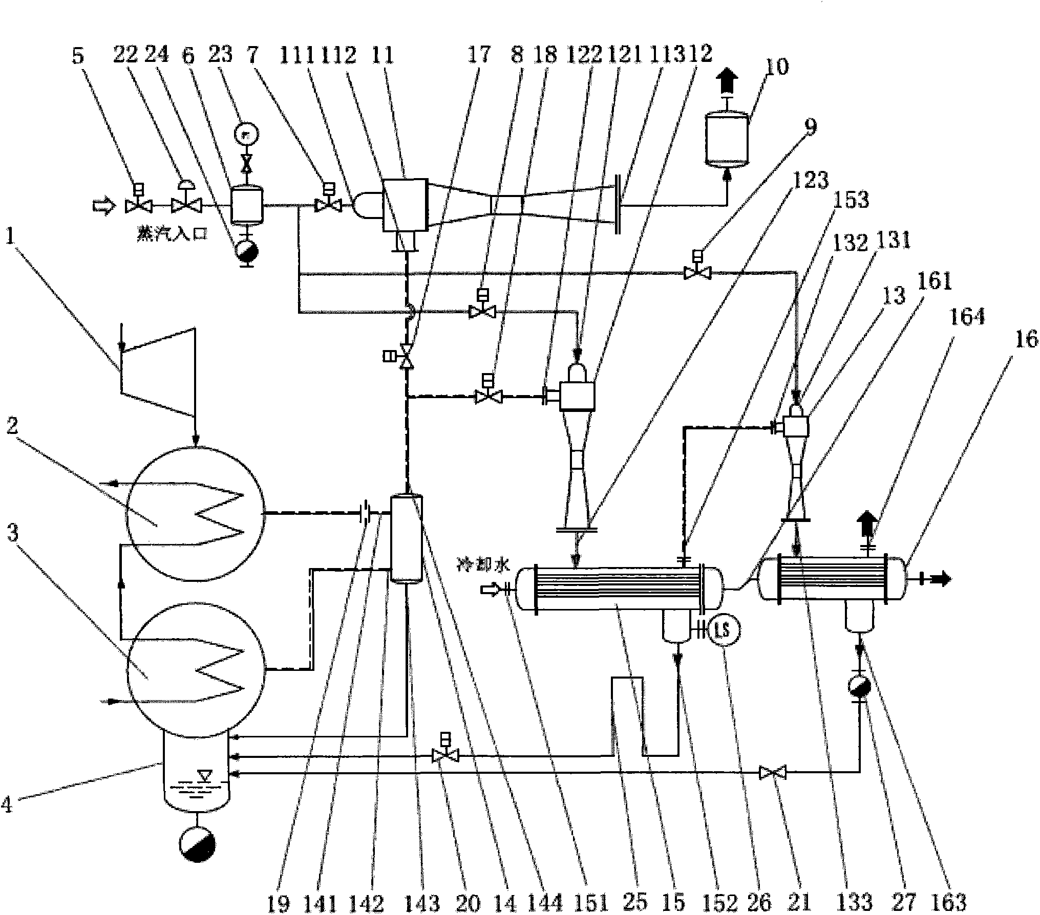
[0100] refer to image 3 , in the double back pressure condenser multi-stage steam injection vacuum pumping system of the present invention, comprising:

[0101] Steam turbine 1, first condenser 2, second condenser 3, power steam surge tank 6, exhaust muffler 10, first steam injector 11, second steam injector 12, third steam injector 13 , a vacuum buffer tank 14, a first steam condenser 15, a second steam condenser 16, a high-pressure side suction line throttle orifice 19, and a plurality of control valves and pipelines arranged between the above-mentioned components;

[0102] The outlet of the steam turbine 1 is connected with the inlet of the first condenser 2 and the inlet of the second condenser 3 at the same time; the first condenser 2 is a high-pressure condenser, and...


PUM


Abstract

The invention provides a multistage steam jet vacuum-pumping system with double backpressure steam condensers. The multistage steam jet vacuum-pumping system comprises a turbine (1), the first steam condenser (2), the second steam condenser (3), a power steam pressure stabilization tank (6), an exhaust silencer (10), a first steam jet device (11), a second steam jet device (12), a third steam jet device (3), a vacuum buffer tank (14), a first condenser (15), a second condenser (16), a high-pressure side air exhaust pipeline restriction orifice (19), and a plurality of control valves and a plurality of pipelines arranged between all the parts mentioned above. Due to the fact that the restriction orifice is arranged on the high-pressure side and the vacuum buffer tank is arranged in the position where the high-pressure side and the low-pressure side are communicated, the pressure difference between the high-pressure side and the low-pressure side is kept. High-temperature steam serves as power for the steam jet devices, output is stable, and the optimal vacuum can be kept for the steam condensers. High-pressure steam serves as power for the steam jet devices, no house supply is needed, the steam jet devices are static devices and almost free of maintenance, and maintenance cost can be reduced.

Description

technical field [0001] The present invention relates to a condenser vacuum pumping system in a power plant, in particular to a multi-stage steam injection vacuum pumping system with double back pressure condensers, especially to a vacuum pumping system with a throttling orifice and Double back pressure condenser multi-stage steam injection vacuum pumping system for vacuum buffer tank. Background technique [0002] The condenser is one of the most important equipment in a power plant. The back pressure of the condenser has an important impact on the economy of the operation of the steam turbine generator set. The vacuum of the condenser of the steam turbine generator set directly affects the steam turbine in the power plant. economic operation. There are many factors affecting the vacuum of the condenser, including the system design arrangement related to the vacuum of the condenser, which affects the quality of the vacuum of the condenser. Multiple condensers have the adva...

Claims


Application Information

Patent Timeline
Patent Type & Authority Applications(China)
IPC IPC(8): F28B9/10
Inventor 张曙光
Owner 普瑞森能源科技(北京)股份有限公司
Why Eureka
Try Eureka