
Method for identifying initial point of density wave oscillation of parallel channel

A technology of channel density and identification method, which is applied in the field of identification of the starting point of density wave pulsation of parallel channels, can solve the problems of inability to realize multi-working conditions, large-scale calculation, low efficiency, etc., and achieve the effect of fast efficiency and high recognition accuracy

Active Publication Date: 2017-12-01
NUCLEAR POWER INSTITUTE OF CHINA
View PDF3 Cites 0 Cited by
  • Summary
  • Abstract
  • Description
  • Claims
  • Application Information

AI Technical Summary

Problems solved by technology

This method requires technicians to manually identify whether density wave pulsation occurs through the flow change curve after each power change, which is extremely inefficient and cannot achieve multi-working conditions and large-scale calculations

Method used


Image

  • Method for identifying initial point of density wave oscillation of parallel channel

Examples


Embodiment 1

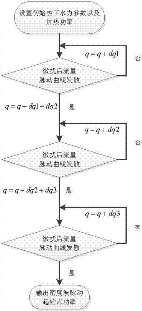
[0025] Such as figure 1 Shown is a parallel channel density wave pulsation starting point identification method, comprising the following steps:

[0026] A. On the basis of the initial thermal hydraulic parameters and heating power, power disturbance is implemented on the channel;

[0027] B. Confirm the divergence of the flow pulsation curve after implementing power disturbance;

[0028] C. If the flow pulsation curve diverges, reduce the heating power; if the flow pulsation curve does not diverge, increase the heating power and reconfirm the divergence of the flow pulsation curve until the flow pulsation curve diverges;

[0029] D. Steps B and C of multiple cycles are used to identify the starting point of density wave pulsation. In multiple cycles, the enhancement of the previous cycle is greater than the enhancement of the next cycle, and the decrement of the cycle is the enhancement of this cycle.

[0030] The initial heating power is less than the starting point of the...

Embodiment 2

[0032] In this embodiment, on the basis of Example 1, the discriminant method for the divergence of the flow pulsation curve is refined, that is, the method for confirming the divergence of the flow pulsation curve in step B is:

[0033] B1. After the time interval dT after the power disturbance is implemented, two time steps dt are continuously taken;

[0034] B2. Obtain the maximum flow and minimum flow of each channel within two time steps dt. The maximum flow in the first time step is Max1, the minimum is Min1, and the maximum flow in the second time step is Max2, the minimum value is Min2;

[0035] B3. Identify the density wave pulsation according to the result of step B2.

[0036] This method is suitable for multiple parallel heating channel structures with constant inlet total flow. Based on the characteristics of divergent flow pulsation, whether it diverges is judged through technical methods in continuous time.

[0037] The time interval dT is 1 second to 2 seconds...


PUM


Abstract

The invention discloses a method for identifying an initial point of density wave oscillation of a parallel channel. The method comprises the following steps: A, power disturbance is performed on the channel on the basis of initial thermal hydraulic parameters and heating power; B, the divergence condition of a flow oscillation curve after implementation of power disturbance is confirmed; C, if the flow oscillation curve diverges, the heating power is reduced; if the flow oscillation curve does not diverge, the heating power is increased and then the divergence condition of the flow oscillation curve is confirmed again until the flow oscillation curve diverges; D, the steps B and C are cycled to identify the initial point of density wave oscillation, enhancement of previous cycle is higher than that of later cycle in the multiple cycles, and the decrement of each cycle is the enhancement of the cycle. According to the method, the heating power is increased or reduced on the basis of the initial thermal hydraulic parameters and heating power, the initial point of density wave oscillation is found out finally, the identification precision is high, identification can be realized through a program, and the efficiency is high.

Description

technical field [0001] The invention relates to the field of reactor thermal hydraulic research, in particular to a method for identifying the starting point of density wave pulsation of a parallel channel. Background technique [0002] The research on the mechanism of thermal-hydraulic characteristics of reactors is the key to the development of reactors, and the problem of flow instability is an important problem that needs to be faced in thermal-hydraulic research. A large number of experiments and theoretical calculations have been carried out to analyze the problem. [0003] At present, there are many programs that can be used to analyze the flow instability of parallel channels, and most of them use the time domain analysis method, that is, by calculating the flow change curves of parallel channels at different power levels to manually judge whether density wave fluctuations occur: if the flow change curve If it is convergent, density wave pulsation does not occur. It...

Claims


Application Information

Patent Timeline
IPC IPC(8): G01N11/04
CPCG01N11/04
Inventor 王艳林鲁晓东袁德文黄彦平
Owner NUCLEAR POWER INSTITUTE OF CHINA
Learn More