
Synthetic aperture radar polarimetric calibration method based on reflection asymmetric information

A synthetic aperture radar, asymmetric technology, applied in the direction of radio wave reflection/re-radiation, using re-radiation, measurement devices, etc., can solve the problem that polarization calibration cannot solve the problem that distributed targets do not meet the reflection symmetry

Inactive Publication Date: 2017-12-01
四川测绘地理信息局测绘技术服务中心
View PDF2 Cites 11 Cited by
  • Summary
  • Abstract
  • Description
  • Claims
  • Application Information

AI Technical Summary

Problems solved by technology

[0004] The purpose of the present invention is to provide a method to solve the problem that the traditional polarization calibration method only satisfies the conditions of terrain undulation and flatness and flight attitude stability, so that the polarization calibration cannot solve the problem that the distributed target does not satisfy the assumption of reflection symmetry

Method used

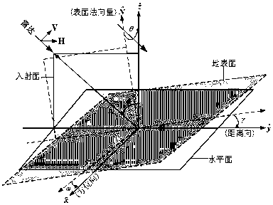

Image

  • Synthetic aperture radar polarimetric calibration method based on reflection asymmetric information
  • Synthetic aperture radar polarimetric calibration method based on reflection asymmetric information
  • Synthetic aperture radar polarimetric calibration method based on reflection asymmetric information

Examples


Embodiment approach 1

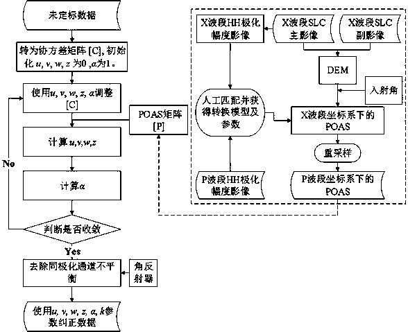
[0054] Figure 1 to Figure 2 Shows: a synthetic aperture radar polarization calibration method reflecting asymmetric information, the method includes the following steps:

[0055] Step 1: Obtain the uncalibrated data matrix [O];

[0056] Step 2: Convert the uncalibrated data into a covariance matrix, and initialize the phasors U, V, W, and Z to 0, Set to 1;

[0057] Step 3: Use initialization phasors U, V, W, Z, Adjust the variance matrix [C];

[0058] Step 4: Obtain the polarization azimuth offset matrix P corresponding to the P band through dual band registration;

[0059] Step 5: Calculate U, V, W, Z according to the offset matrix P;

[0060] Step 6: calculate again

[0061] Step 7: Use the corner reflector to judge Whether to converge, if it converges, remove the imbalance of the co-polarization channel, go to step 8; if it does not converge, use the initialization phasor U, V, W, Z, Adjust the variance matrix [C], obtain the polarization azimuth offset matrix P corresponding to...

Embodiment approach 2

[0065] On the basis of embodiment 1, the data matrix of synthetic aperture radar described in step 1 includes VV channel echo data of synthetic aperture radar, VH channel echo data of synthetic aperture radar, HH channel echo data of synthetic aperture radar, and synthetic aperture radar. HV channel echo data of aperture radar.

[0066] In this embodiment, the composition of the matrix parameters of the synthetic aperture radar is described in detail, that is, the O phasor is The Z phasor is

Embodiment approach 3

[0068] On the basis of embodiment 1, in step 3, the variance matrix [C]=[O][O] H .

[0069] This embodiment details the solution process of the variance matrix [C].


PUM


Abstract

The invention discloses a synthetic aperture radar polarimetric calibration method based on reflection asymmetric information, which includes the following steps: getting an uncalibrated data matrix [O]; converting the uncalibrated data matrix into a covariance matrix, and setting initialization phasors U, V, W and Z to 0 and inverted 'e' (partial) to 1; using the initialization phasors U, V, W, Z and inverted 'e' to adjust a variance matrix [C]; getting a polarization azimuth deviation matrix P corresponding to a P band through dual-band registration; calculating U, V, W and Z according to the deviation matrix P; and calculating inverted 'e'. The traditional polarimetric calibration method can only meet the conditions of smooth terrain fluctuation and stable flight attitude, and thus, the problem that a distributed target fails to meet a reflection symmetry hypothesis cannot be solved through polarimetric calibration. The problem in the prior art is solved using the method of the invention.

Description

Technical field [0001] The invention relates to a SAR radar polarization calibration method, in particular to a synthetic aperture radar polarization calibration method reflecting asymmetric information. Background technique [0002] Few people involved the processing method of reflected asymmetry information before calibration. Kimura uses the power value to exclude the reflection asymmetry of the building area and the remaining use area participates in the calibration (Kimura et al., 2004). Freeman assumes the system error before calibration. Based on this, Gao Xiao proposed an estimation method of Faraday rotation (Freeman, 2004). Domestic scholars have tried to substitute the flight attitude angle into Whitt's algorithm (Zhang Lintao et al., 2011). Under normal circumstances, the flight pitch angle will not exceed 10°, and the ground slope is much more than this in many times and in many areas. Therefore, the calibration of the airborne platform needs to consider more the re...

Claims


Application Information

Patent Timeline
Patent Type & Authority Applications(China)
IPC IPC(8): G01S13/90G01S7/40
CPCG01S7/40G01S13/9023G01S13/9076
Inventor 黄瑞金陈莉向筱程多祥何晓祯周兴霞廖露李建周凯赵祯
Owner 四川测绘地理信息局测绘技术服务中心
Learn More