Flyback converter with no need for the auxiliary winding

A flyback converter and auxiliary winding technology, applied in the field of flyback converters, can solve the problems of providing continuous and stable, relaxed output voltage regulation rate, etc.

Inactive Publication Date: 2017-12-01
产晶积体电路股份有限公司
View PDF4 Cites 1 Cited by
  • Summary
  • Abstract
  • Description
  • Claims
  • Application Information

AI Technical Summary

Problems solved by technology

PSR uses magnetic coupling to the primary side to adjust the output voltage, and does not require a feedback control circuit based on an optocoupler on the secondary side, but has the disadvantage of a relatively relaxed output voltage regulation rate
[0004] Moreover, conventional flyback converters generally allow the primary switch to be driven by a low-side drive (Low-Side Drive, LSD), which drives the primary-side switch disposed on the low-voltage side of the primary-side winding, requiring an auxiliary winding on the primary side , because the primary side winding cannot replace the auxiliary winding to provide a continuous and stable operating voltage to the IC controller on the primary side after startup

Method used


Image

  • Flyback converter with no need for the auxiliary winding
  • Flyback converter with no need for the auxiliary winding
  • Flyback converter with no need for the auxiliary winding

Examples


Embodiment Construction

[0053] The following describes the embodiments of the present invention in more detail in conjunction with the drawings and component symbols, so that those skilled in the art can implement them after studying this specification.

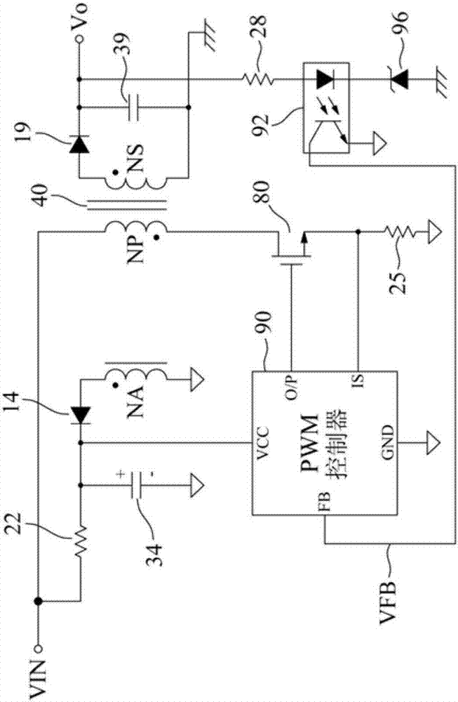
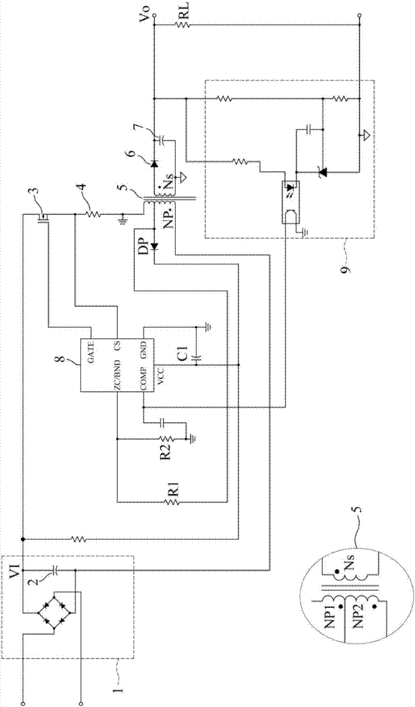
[0054] due to Figure 4 In addition to the PWM controller with image 3 Many of the same features, among them image 3 Use a 6-pin PWM controller and Figure 4 Using 8-pin PWM controller, the following description will only image 3 A more detailed explanation is provided to clearly demonstrate the technical features of the present invention.

[0055] See image 3 , Which illustrates a flight structure built around a 6-pin PWM controller according to the present invention without auxiliary winding-high-side drive-secondary side regulation (Auxiliary-Free High-Side Driven Secondary-Side Regulated, AF-HSD-SSR) Back to the converter. The AF-HSD-SSR flyback converter of the present invention includes: AC-to-DC rectifier unit 1, input capacitor 2, switching...


PUM


Abstract

Disclosed is an Auxiliary-Free High-Side Driven Secondary-Side Regulated (AF-HSD-SSR) flyback converter, which includes an AC-to-DC rectification unit, an input capacitor, a switching unit, a current-sensing resistor, an Auxiliary-Free (AF) flyback transformer, an output rectifier, an output capacitor, a PWM controller, and a SSR unit. The AF flyback transformer includes a primary winding and a secondary winding, where the primary winding is split into two halves. The switching unit is placed at the high side of the primary winding, and the PWM controller in collocation with the SSR unit drives the switching unit in response to all the required voltage and current sense signals to keep voltage conversion and power delivery safe and efficient within the specifications. The first half of the primary winding can provide the PWM controller with a continuous and steady working voltage supply after startup, thus eliminating the need for the auxiliary winding.

Description

Technical field [0001] The invention relates to a flyback converter, especially a flyback converter that does not require auxiliary windings in a flyback transformer, which can greatly simplify the structure of the transformer and reduce the cost of the transformer. Background technique [0002] Various DC electrical devices, such as integrated circuits (ICs), DC motors, or liquid crystal displays without a suitable DC voltage source, require appropriate voltage converters, such as flyback conversion for DC to DC voltage conversion A flyback converter, a forward converter or an LLC converter converts the rectified AC voltage source into a specific DC voltage level to supply power to them. [0003] In the prior art, the flyback converter usually uses Secondary-Side Regulation (SSR) or Primary-Side Regulation (PSR) to regulate the output voltage. SSR uses optical coupling from the secondary side to adjust the output voltage, and requires a feedback control circuit based on an optica...

Claims


Application Information

Patent Timeline
Patent Type & Authority Applications(China)
IPC IPC(8): H02M3/335
CPCH02M3/33523H02M1/36H02M1/0006H02M1/08H02M1/0009
Inventor 王志良余金生彭文彦
Owner 产晶积体电路股份有限公司
Why Eureka
Try Eureka