Safety device operation timing control method and device

A safety device and timing control technology, applied in the directions of pedestrian/occupant safety arrangement, measurement device, control device, etc., can solve the problem of drivers' troubles about safety device work

Active Publication Date: 2017-12-01
DENSO CORP +1
View PDF9 Cites 10 Cited by
  • Summary
  • Abstract
  • Description
  • Claims
  • Application Information

AI Technical Summary

Problems solved by technology

[0005] The conventional PCS system may activate the safety device despite the driver's intention to avoid a collision. In this case, the driver may be troubled by the operation of the safety device.

Method used


Image

  • Safety device operation timing control method and device
  • Safety device operation timing control method and device
  • Safety device operation timing control method and device

Examples


no. 1 approach >

[0027] The driving assistance device according to the present embodiment is installed in the vehicle (host vehicle) 40, and determines whether there is an object around the traveling direction (for example, in front) of the own vehicle, and when it is determined that there is an object, performs driving assistance As a method, the PCS system that performs control to avoid the collision between the target object and the host vehicle 40 or to reduce the collision damage functions.

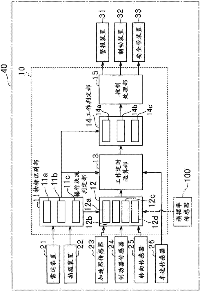
[0028] exist figure 1 Among them, the driving assistance ECU 10 as a driving assistance device is a computer including a CPU, a memory (including ROM and RAM), I / O, and the like. The driving assistance ECU 10 realizes various functions described later by the CPU executing, for example, a program installed in the ROM.

[0029] A radar device 21 , an imaging device 22 , an accelerator sensor 23 , a brake sensor 24 , a steering sensor 25 , and a vehicle speed sensor 26 are connected to the driving assi...

no. 2 approach >

[0108]The overall configuration of the driving assistance ECU 10 constituting the driving assistance device according to the second embodiment is the same as that of the driving assistance ECU 10 according to the first embodiment, but a part of the functions of the driving assistance ECU 10 according to the second embodiment and A part of the driving assistance processing is different from a part of the functions of the driving assistance ECU 10 and the driving assistance processing according to the first embodiment.

[0109] Figure 5 It is a flowchart showing an example of driving assistance processing executed by the driving assistance ECU 10 according to the second embodiment. This driving assistance process is performed for each object existing in the traveling direction of the host vehicle 40 every predetermined control cycle. In addition, in Figure 5 In , "timing" also refers to the threshold corresponding to the timing. exist Figure 5 In the driving assistance pr...

no. 3 approach >

[0119] The overall configuration of the driving assistance ECU 10 constituting the driving assistance device according to the third embodiment is the same as that of the driving assistance ECU 10 according to the first embodiment, but a part of the functions of the driving assistance ECU 10 according to the third embodiment and A part of the driving assistance processing is different from a part of the functions of the driving assistance ECU 10 and the driving assistance processing according to the first embodiment.

[0120] The operation state determination unit 12 of the driving assistance ECU 10 according to the third embodiment includes a road shape determination unit 12c (in figure 1 shown in dotted line).

[0121] Such as Image 6 As shown, the road shape determination unit 12c extracts the lane line 50 such as the white line drawn on the road in the traveling direction of the host vehicle 40 from the second detection information. Then, the road shape determination uni...


PUM


Abstract

In a safety device operation timing control device, if a collision avoidance operation in the longitudinal direction is determined to have been carried out, a configuration unit configures a first timing, which is a timing slower than a reference timing, which is a timing for operating the safety device, and meanwhile, if a collision avoidance operation in the horizontal direction is determined to have been carried out, the configuration unit configures a second timing, which is a timing later than the aforementioned reference timing. Further, in the case that a collision avoidance operation in the longitudinal direction and/or a collision avoidance operation in the horizontal direction is determined to have been carried out, then an operation determination unit makes a determination about whether or not to operate the safety device on the basis of the corresponding first timing and/or second timing.

Description

technical field [0001] The present invention relates to a safety device operation timing control method and device for controlling the operation timing of a safety device included in a self-vehicle based on the possibility of a collision between the self-vehicle and an object located in the traveling direction of the self-vehicle. Background technique [0002] Conventionally, there is known a pre-crash safety (PCS) system that reduces or prevents collision damage between an own vehicle and obstacles (objects) such as other vehicles, pedestrians, or road structures located in front of the own vehicle in the traveling direction. This PCS system calculates a time to collision (TTC) which is a margin time until the own vehicle collides with the obstacle based on the relative distance between the own vehicle and the obstacle and the relative speed or relative acceleration. Then, based on the calculated predicted collision time, the PCS system notifies the driver of the own vehicl...

Claims


Application Information

Patent Timeline
Patent Type & Authority Applications(China)
IPC IPC(8): B60R21/0134B60R21/00B60T7/12G01S13/86G01S13/93G08G1/16G01S13/931
CPCB60T7/12B60R21/0134B60T7/22G01S13/867G01S13/931B60T2201/022G08G1/166G01S2013/93185G01S2013/9318B60W2552/20B60W10/18B60W10/30B60W30/09B60W30/0953B60W50/087B60W50/14B60W2540/10B60W2540/12
Inventor 峰村明宪伊东洋介池涉根本和希
Owner DENSO CORP
Why Eureka
Try Eureka