Supercharge Your Innovation With Domain-Expert AI Agents!

Contoured bushings for flame face burners

A liner and shape technology, which is applied in the field of fixed shape liner of flame front burner, can solve problems such as changes and obstacles

Active Publication Date: 2019-11-05
H2 IP英国有限公司
View PDF23 Cites 0 Cited by
  • Summary
  • Abstract
  • Description
  • Claims
  • Application Information

AI Technical Summary

Problems solved by technology

[0005] However, although premixing fuel and air prior to combustion has been shown to contribute to lower emissions, the amount of fuel-air premix injected has a tendency to vary due to various combustor variables
Therefore, there are still barriers to controlling the amount of fuel-air premix that is injected into the combustor

Method used


Image

  • Contoured bushings for flame face burners
  • Contoured bushings for flame face burners
  • Contoured bushings for flame face burners

Examples


Embodiment Construction

[0029] This application incorporates the subject matter of US Patent Nos. 6,935,116, 6,986,254, 7,137,256, 7,237,384, 7,308,793, 7,513,115, and 7,677,025 by reference.

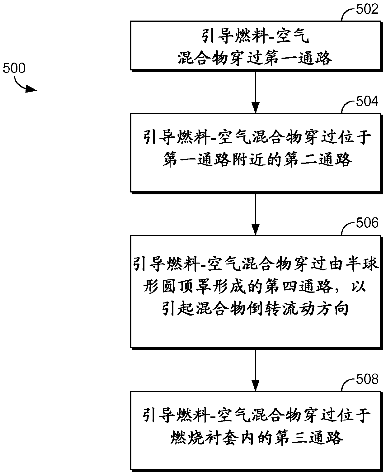
[0030] A system and method for controlling the velocity of a fuel-air mixture injected into a combustion system is disclosed. That is, the predetermined effective flow area is maintained by two coaxial structures forming an annulus of known effective flow area through which the fuel-air mixture passes.

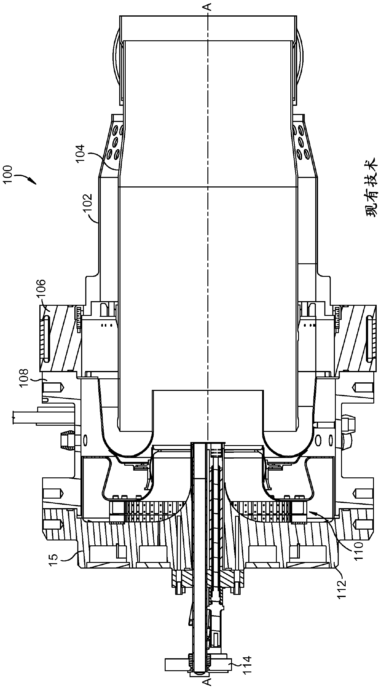
[0031] will now be about Figure 2-8 to discuss the present invention. figure 2 An embodiment of a gas turbine combustion system 200 in which the present invention operates is depicted in FIG. The combustion system 200 is an example of a multi-stage combustion system and extends about a longitudinal axis A-A and includes a generally cylindrical flow sleeve 202 for directing a predetermined amount of compressor air. The combustion liner 204 has an inlet end 206 and an opposite outlet end 208 . Combustion ...


PUM


Abstract

The present invention discloses a novel apparatus and method for reducing the recirculation area at the inlet end of the burner. The recirculation area is reduced by changing the geometry of the inlet end to reduce the blunt body effect at the inlet end of the combustion liner via tapering of the liner wall thickness and tapering of the thermal barrier coating.

Description

technical field [0001] The present invention generally relates to an apparatus and method for directing a fuel-air mixture into a combustion system. More specifically, the hemispherical dome is positioned near the inlet of the combustion liner to direct the fuel-air mixture in a more efficient manner to better control the rate at which the fuel-air mixture enters the combustion liner while allowing the combustion liner Unfavorable aerodynamic effects in the inlet area are as small as possible. Background technique [0002] In order to reduce the amount of polluting emissions from gas-powered turbines, government agencies have enacted numerous regulations requiring reductions in the amount of nitrogen oxides (NOx) and carbon monoxide (CO). Lower combustion emissions are generally attributable to a more efficient combustion process, particularly with regard to fuel injector position, air flow rate, and mixing effectiveness. [0003] Older combustion systems used diffusion-ty...

Claims


Application Information

Patent Timeline
Patent Type & Authority Patents(China)
IPC IPC(8): F23R3/42F23R3/00
CPCF23R3/002F23R3/286F23R3/46F23R3/54F05D2240/35
Inventor P.J.斯图塔福德H.里兹卡拉
Owner H2 IP英国有限公司
Features
  • R&D
  • Intellectual Property
  • Life Sciences
  • Materials
  • Tech Scout
  • Unparalleled Data Quality
  • Higher Quality Content
  • 60% Fewer Hallucinations
Learn More