Coil part

A technology of coil components and recesses, applied in the direction of transformer/inductor parts, electrical components, transformer/inductor coils/windings/connections, etc., can solve the problem of large mode conversion characteristics and reduce the mode conversion characteristics. , the effect of reducing stray capacitance

Active Publication Date: 2017-12-01
MURATA MFG CO LTD
View PDF5 Cites 15 Cited by
  • Summary
  • Abstract
  • Description
  • Claims
  • Application Information

AI Technical Summary

Problems solved by technology

[0013] In the common mode choke coil 41 described above, when the frequency of the signal input to it becomes higher, the ratio of the input differential signal component that is converted into common mode noise and outputted, that is, the mode conversion characteristic, may be expressed poorly. Big
[0014] The same problem is not limited to common mode choke coils, for example, the same problem can be encountered in a wire-wound chip transformer with the same first and second wires

Method used


Image

  • Coil part
  • Coil part
  • Coil part

Examples


Embodiment Construction

[0037] First, regarding the above-mentioned problem of increase in the mode conversion characteristic (hereinafter referred to as "Scd21"), the contents discovered by the inventors of the present application will be described below.

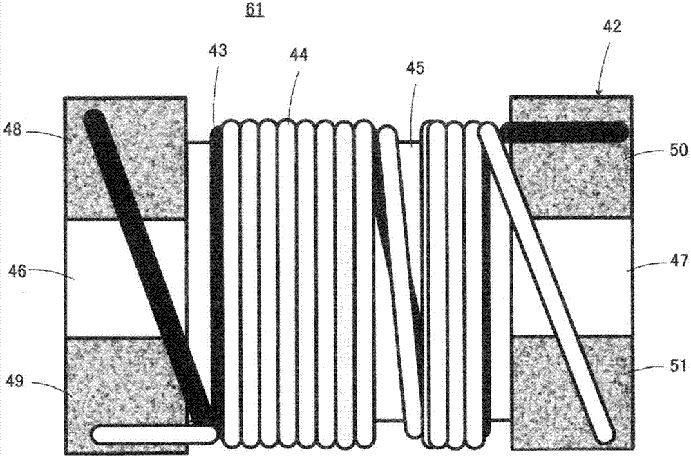
[0038] The cause of the above-mentioned problem is that the stray capacitance (distributed capacitance) generated in association with the common mode choke coil 41 breaks the balance of the signal passing through the common mode choke coil 41 .

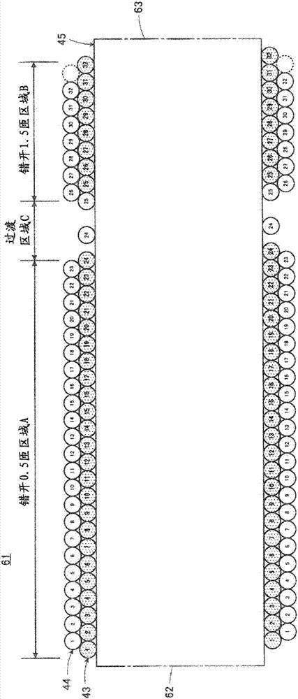
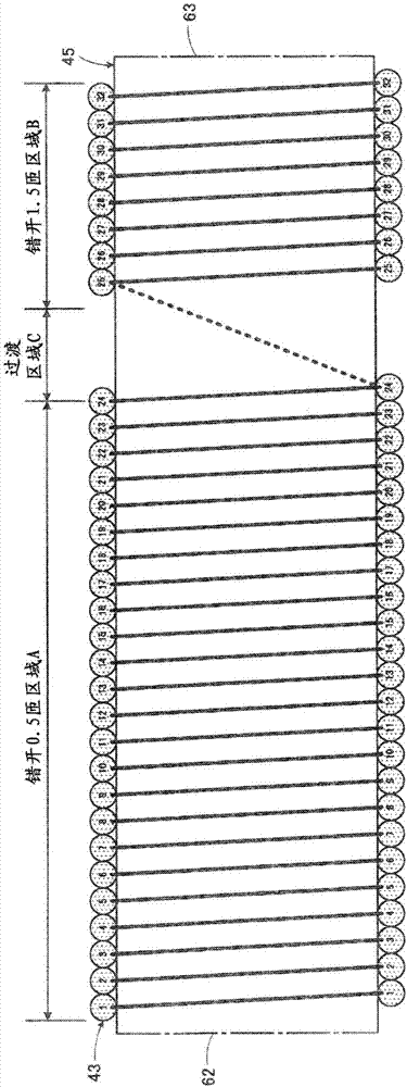
[0039] First, refer to Figure 11 as well as Figure 12 The stray capacitance generated in the common mode choke coil 41 will be described in more detail. exist Figure 11 In , a part of the winding state of the first wire 43 and the second wire 44 on the winding core portion 45 is enlargedly shown in a cross-sectional view. exist Figure 11 In , the numerals marked in the respective sections of the first line 43 and the second line 44 indicate the number of turns. That is, in Figure 11 In , the f...


PUM


Abstract

In a winding-type common mode choke coil serving as an example of a coil part, troubles such as mode conversion characteristics becoming larger due to the effects of stray capacitance are eliminated. A 0.5 shift region A which shifts 0.5 turns between a first wire (43) of a first layer and a second wire (44) of a second layer, and a 1.5 shift region B which shifts 1.5 turns in the opposite direction are distributed on a winding coil section (45) along the axial direction. In the 0.5 shift region A, a diagonal capacity which is quantified as -1 or +1 is generated for each one turn, and in the 1.5 shift region B, a diagonal capacity which is quantified as +3 or -3 is generated for each one turn. Here, the sum of the number of turns of the second wire (44) positioned in the 0.5 shift region A is set to be at least two times and at most five times the sum of the number of turns of the second wire positioned in the 1.5 shift region B, thereby balancing the diagonal capacity over the entirety of the first and second wires to reduce the effects of stray capacitance.

Description

technical field [0001] The present invention relates to a coil component, and particularly relates to an improvement regarding the winding method of the wire in a wire-wound coil component having a structure in which two wires are wound around a winding core. Background technique [0002] A typical example of the coil component according to the present invention is a common mode choke coil. [0003] The common mode choke coil of interest in the present invention is described in, for example, Japanese Patent No. 4789076 (Patent Document 1). exist Figure 9 The external appearance of the common mode choke coil 41 which has basically the same structure as the structure described in patent document 1 is shown in . [0004] Such as Figure 9 As shown, the common mode choke coil 41 is provided with the core 42, the 1st wire (wire) 43, and the 2nd wire 44 which respectively comprise an inductor. The core 42 is made of an electrically insulating material, more specifically, alumin...

Claims


Application Information

Patent Timeline
IPC IPC(8): H01F17/04H01F27/28
CPCH01F17/045H01F27/006H01F27/2823H01F27/24H01F27/34
Inventor 宫本昌史山本滋人山口健太郎
Owner MURATA MFG CO LTD
Why Eureka
Try Eureka