

X-ray tube device
An X-ray tube and X-ray technology, applied in the field of X-ray tube devices, can solve the problems of shortened filament life and rise in filament operating temperature
- Summary
- Abstract
- Description
- Claims
- Application Information
AI Technical Summary
Problems solved by technology
Method used
Image

Examples
no. 1 approach
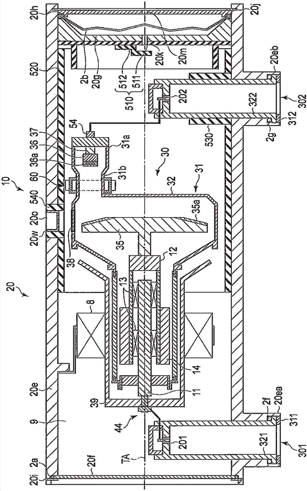
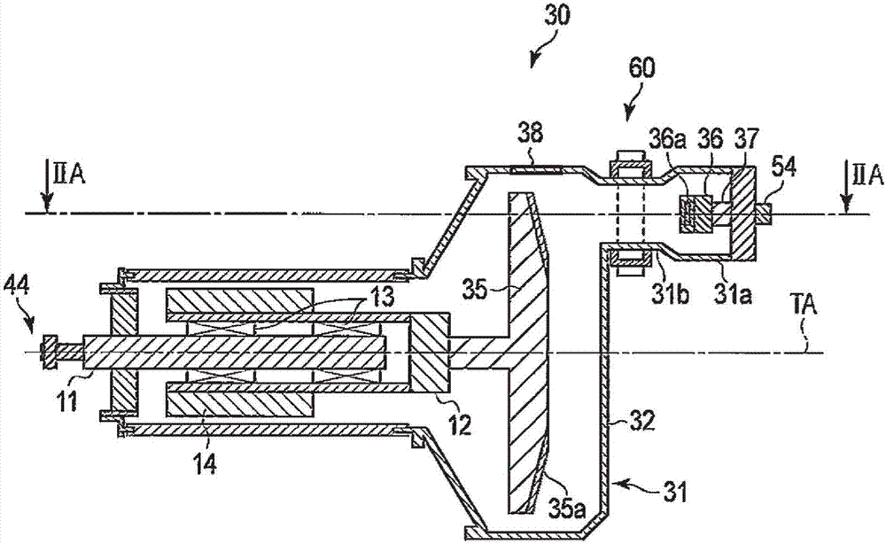
[0043] figure 1 It is a sectional view showing an example of the X-ray tube device 10 according to the first embodiment.
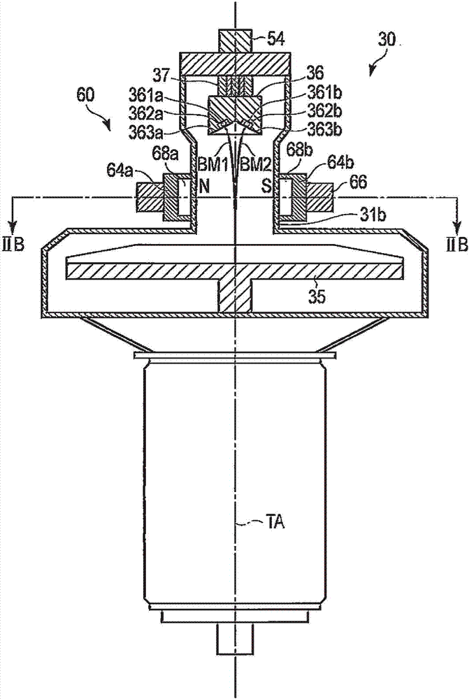
[0044] Such as figure 1 As shown, the X-ray tube device 10 of the first embodiment generally includes: a stator coil 8; a casing 20; an X-ray tube 30; a high-voltage insulating member 39; a quadrupole magnetic field generating part 60; Radiation shielding parts 510 , 520 , 530 , 540 . For example, the X-ray tube device 10 is a rotating anode side X-ray tube device. The X-ray tube 30 is, for example, a rotating anode type X-ray tube. The X-ray tube 30 is, for example, a neutral-point grounded rotating anode X-ray tube. The X-ray shielding parts 510, 520, 530, and 540 are formed of lead, respectively.
[0045] In the X-ray tube device 10 , a space formed between the inside of the casing 20 and the outside of the X-ray tube 30 is filled with insulating oil 9 as a cooling liquid. For example, the X-ray tube 10 is cooled by circulating the insulating oil ...
Deformed example 1
[0122] An X-ray tube device 1 according to Modification 1 of the first embodiment includes a filament in addition to the configuration of the first embodiment.
[0123] Figure 4A It is a cross-sectional view showing the outline of an X-ray tube according to Modification 1 of the first embodiment, Figure 4B is a cathode diagram of Modification 1 of the first embodiment, Figure 4C It is a cross-sectional view along line IVA-IVA.
[0124] The cathode 36 of the modified example includes a filament 361c, a converging groove 362c, and a converging surface 363c in addition to the structure of the first embodiment. Here, the filament 361c is provided so as to face the anode target 35 between the aforementioned filaments 361a and 361b. In addition, in this embodiment, all the cathodes 36 emit electron beams at the same time, but it is also possible to select and adjust a filament that emits electron beams from a plurality of provided filaments.
[0125] When a negative high volt...
no. 2 approach
[0136] The X-ray tube device 1 of the second embodiment includes, in addition to the structure of the first embodiment, a coil for deflecting an electron beam.
[0137] Figure 5 It is a figure which shows the outline of the X-ray tube apparatus of 2nd Embodiment.
[0138] Such as Figure 5 As shown, the quadrupole magnetic field generating unit 60 of the second embodiment further includes deflection coil units 69a, 69b.
[0139] The quadrupole magnetic field generating unit 60 generates a dipole direct current magnetic field in which the magnetic fields generated from two paired magnetic poles are in the same direction. The quadrupole magnetic field generator 60 includes a pair of magnetic poles 68a and 68c, and a pair of magnetic poles 68b and 68d. The magnetic pole pairs 68a, 68c and the magnetic pole pairs 68b, 68d form a magnetic field as dipoles, respectively. The quadrupole magnetic field generator 60 further superimposes the DC magnetic field on the DC magnetic fie...
PUM
 Abstract
Description
Claims
Application Information