Method and apparatus for fault propagation in section protection

A fault and protection domain technology, applied in transmission systems, digital transmission systems, time-division multiplexing systems, etc., can solve the problems of operators such as useless fault diagnosis procedures, reporting false primary alarms, and being unable to be informed of I1 node isolation conditions, etc.

Active Publication Date: 2020-06-26
HUAWEI TECH CO LTD
View PDF6 Cites 0 Cited by
  • Summary
  • Abstract
  • Description
  • Claims
  • Application Information

AI Technical Summary

Problems solved by technology

[0026] However, there may be some cases where peer interconnect node I3 cannot be informed about the isolation of node I1: for example, when interconnect node I1 detects a unidirectional failure, but there is no When the situation is notified to the relevant protocol (for example, the Distributed Resilient Network Interconnect (DRNI) protocol) of the peer interconnection node I3
[0027] Furthermore, failure to receive an expected CCM message at e.g. node E will likely cause node E to report a false primary warning to the operator
The result would be that the operator triggers a useless and expensive troubleshooting procedure, only to find that there is no fault to fix in the protection domain between node E and interconnect node I1
[0028] In addition, for the transmission of protection switching events that may occur across multiple protection domains, the traffic forwarding problem involved in it has not been solved in the prior art

Method used


Image

  • Method and apparatus for fault propagation in section protection
  • Method and apparatus for fault propagation in section protection
  • Method and apparatus for fault propagation in section protection

Examples


Embodiment Construction

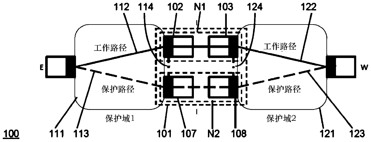
[0076] figure 1 A system 100 according to a first embodiment of the invention is shown.

[0077] specifically, figure 1 An interconnection node N1 for interconnecting the first protection domain 111 and the second protection domain 121 is shown. The second protection domain 121 includes a working path 122 and a protection path 123, and the protection path 123 provides linear protection for a network that forwards traffic between two end nodes. In this configuration, interconnect node N1 is interposed between end node E and end node W, which are remote nodes of N1 within the first protection domain and the second protection domain, respectively. In other configurations that include more than two protection domains, remote nodes can also be interconnected nodes, as will be referred to later Figure 9 with Figure 10 for a more detailed description. An end node is a node located at the end of the domain of interest within which segment protection is implemented. Depending o...


PUM


Abstract

The present invention proposes an interconnection node for interconnecting a first protection domain and a second protection domain, wherein the second protection domain includes a working path and a protection path, and the protection path is used for traffic forwarding between two end nodes Linear protection in the network. The interconnection node includes at least one interface and monitoring unit. The interface is used to receive first monitoring information from the first protection domain; the monitoring unit is used to detect the isolation status of the interconnection node in the first protection domain according to the first monitoring information, and generate second monitoring information and send the second The monitoring information is sent to the working path, so that a fault on the working path can be detected at a remote node of the working path according to the second monitoring information. If this isolation state is detected, the monitoring unit starts to send alarm indication information to the working path, so as to suppress the alarm report about the failure on the working path at the remote node.

Description

technical field [0001] The present invention generally relates to the field of traffic forwarding between two end nodes, and more particularly to the interconnection between protection domains in a network where traffic is forwarded between two end nodes. Further, the present invention relates to an interconnection node interconnecting protection domains, and a method for interconnecting protection domains. The technical field of the technology involved in the present invention covers: packet transmission, protection switching (protection switching), packet network (such as, Ethernet or based on Multi-Protocol Label Switching-Transport Profile (Multi-Protocol Label Switching-Transport Profile, MPLS-TP ) network), and time-division multiplexing (Time-Division Multiplexing, TDM) technology (eg, Optical Transport Network (Optical Transport Network, OTN) or Synchronous Digital Hierarchy (Synchronous Digital Hierarchy, SDH)). Background technique [0002] When the protection dom...

Claims


Application Information

Patent Timeline
Patent Type & Authority Patents(China)
IPC IPC(8): H04L12/715H04L12/707H04L12/703H04L45/24H04L45/28H04L45/50
CPCH04L45/04H04L45/24H04L45/28H04L45/22H04J3/1652H04J14/0268H04J14/0273H04L45/50
Inventor 伊塔洛·布希叶敏
Owner HUAWEI TECH CO LTD
Why Eureka
Try Eureka