A milling chatter test piece and its testing method

A technology of milling chatter and test method, which is applied in the direction of measuring/indicating equipment, metal processing machinery parts, metal processing equipment, etc., can solve the problems of process parameters such as milling chatter, and achieve the effect of simple and reliable test and simple test method

Active Publication Date: 2019-03-05
CHENGDU AIRCRAFT INDUSTRY GROUP
View PDF14 Cites 0 Cited by
  • Summary
  • Abstract
  • Description
  • Claims
  • Application Information

AI Technical Summary

Problems solved by technology

[0006] The purpose of the present invention is to provide a milling chatter test piece and its testing method, which is used to solve the problem of milling chatter caused by machine tool characteristics, intermittent milling, and unreasonable setting of process parameters in CNC milling.

Method used


Image

  • A milling chatter test piece and its testing method
  • A milling chatter test piece and its testing method
  • A milling chatter test piece and its testing method

Examples


Embodiment 1

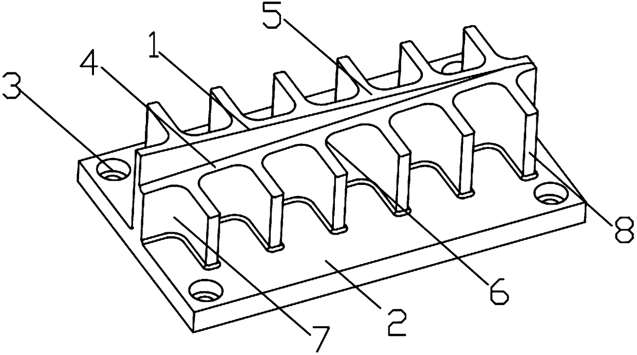
[0028] combined with figure 1 , attached figure 2 As shown, a milling chatter test piece, a milling chatter test piece, includes a base 2, and the base 2 is provided with a through hole 3 for fixing the base 2; the upper surface of the base 2 A milling test body 1 with two or more than two T-shaped test areas on the side is fixed, the upper surface of the milling test body 1 is provided with a slope and a reference plane 5, and a circle is provided at the bend of the T-shaped test area. Corner test area, where the intersection of the T-shaped test area and the bottom end of the slope is the milling area 7 .

[0029] Structural principles:

[0030] The test body 1 is placed on the base 2 of the milling chatter test piece, and the base 2 is fixed on the machine tool through the through hole 3. There are two or more T-shaped test areas on the side of the test body 1. The tool moves from T-shaped test area milling, the T-shaped test area can test the chatter of milling, the up...

Embodiment 2

[0032] In order to ensure the stability and continuity of the milling process, on the basis of the structure and principle of Embodiment 1, further combined with the attached figure 1 , attached figure 2 As shown, the T-shaped test area in this embodiment also includes a straight line test area and an over-rounded corner 8, the over-rounded corner 8 is arranged at the end of the straight line test area, and the reference plane 5 is perpendicular to the tool.

[0033] Structural principles:

[0034] Because the shape of the test area is T-shaped, in order to ensure the stability and continuity of the milling process, the end face of the T-shaped test area is provided with an excessive fillet 8, and the tool can directly mill the excessive circle on the T-shape after milling out of the straight line test area Angle 8, to maintain the continuity of milling. In order to obtain stable test parameters and facilitate the detection of milling chatter, datum plane 5 is perpendicular ...

Embodiment 3

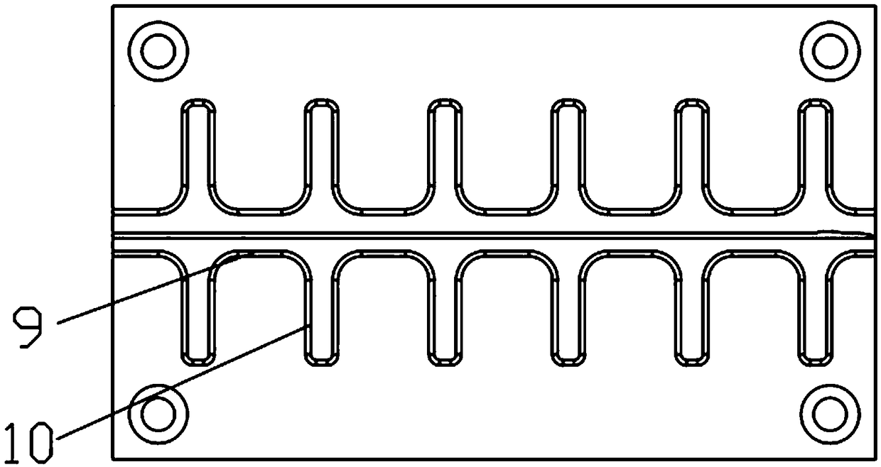
[0036] In order to better monitor the milling chatter of the tool in the fillet test area, on the basis of the structure and principle of Embodiment 1, further combined with the attached figure 1 , attached figure 2 As shown, the fillet test area in this embodiment includes a fillet milling area 9, a test fillet 6, and a fillet milling area 10, and the fillet milling area 9 and the fillet milling area 10 are respectively set On both sides of the test fillet 6.

[0037] Structural principles:

[0038] During the milling chatter test, the tool first passes through the fillet milling area 9, and after a certain distance of linear milling in the fillet milling area 9, the tool enters the fillet test area to ensure the stability of the chatter test at the fillet milling area , Fillet milling area 10 ensures that the tool mills out smoothly at the fillet.


PUM


Abstract

The invention discloses a milling chatter test piece and method. The milling chatter test piece is provided with a datum plane and a slope, and the datum plane and the slope are covered with T-shaped test areas. The T-shaped test areas are internally provided with linear test area bodies and rounded-corner test area bodies. According to the milling chatter test method, a tool mills the T-shaped test areas covering the slope at first, the milling depth obtained when chatter is generated is measured, the milling depth of the tool is adjusted, the T-shaped test areas in the datum plane are milled, the datum plane is mainly used for measuring the milling chatter condition of the milling depth at which no chatter is generated when the slope is milled in the linear test area bodies and the rounded-corner test area bodies of the datum plane, and accordingly stable parameters are obtained; and in order to avoid chatter during machining, the milling depth needs to be kept below the former milling depth value, the test part can measure different rounded corners, the formation angles of the rounded corners and the milling chatter condition during height milling, the testing is simple, convenient to implement and reliable, and complex measurement and analysis facilities are not required.

Description

technical field [0001] The invention relates to the field of machining, in particular to a milling chatter test piece and a test method thereof. Background technique [0002] In the machining of aerospace structural parts, contour milling is widely used, but in contour milling, the problem of fillet milling is very prominent. Unreasonable cutting parameters often cause chatter at the fillet milling place, which is very easy to damage the tool and parts. [0003] Milling chatter is a major factor that restricts the improvement of high-speed milling efficiency. The occurrence of milling chatter is closely related to the processing parameters such as spindle speed, milling depth and machine characteristics during milling. In order to avoid milling chatter in actual machining, the method of reducing milling parameters is often used, which greatly limits the efficiency of high-speed milling. Different machine tools have different characteristics and have different effects on mil...

Claims


Application Information

Patent Timeline
Patent Type & Authority Patents(China)
IPC IPC(8): B23Q17/12
CPCB23Q17/12
Inventor 何磊陈建波李小兵高锦焜马南峰李仁政
Owner CHENGDU AIRCRAFT INDUSTRY GROUP
Why Eureka
Try Eureka