
Test equipment for cooperative mechanical arm driving controller board

A technology for driving controllers and testing equipment, applied in the directions of manipulators, manufacturing tools, etc., can solve the problem of low efficiency in detecting the driving controller board, and achieve the effect of simplifying the testing method and improving the testing efficiency.

Pending Publication Date: 2021-03-26
SHENZHEN YUEJIANG TECH CO LTD
View PDF0 Cites 1 Cited by
  • Summary
  • Abstract
  • Description
  • Claims
  • Application Information

AI Technical Summary

Problems solved by technology

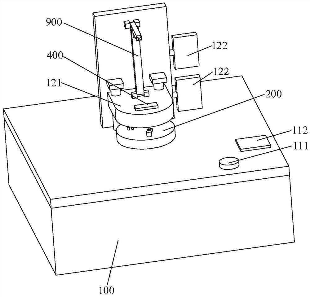
[0004] The main purpose of the present invention is to provide a test device for a cooperative manipulator drive controller board, aiming to solve the technical problem of low efficiency of the existing detection drive controller board

Method used


Image

  • Test equipment for cooperative mechanical arm driving controller board
  • Test equipment for cooperative mechanical arm driving controller board
  • Test equipment for cooperative mechanical arm driving controller board

Examples


Embodiment Construction

[0028] Embodiments of the present invention are described in detail below, examples of which are shown in the drawings, wherein the same or similar reference numerals designate the same or similar elements or elements having the same or similar functions throughout. The embodiments described below by referring to the accompanying drawings are exemplary and are intended to explain the present invention, but cannot be construed as limitations to the present invention. Based on the embodiments in the present invention, those of ordinary skill in the art have no creative work All other embodiments obtained under the premise all belong to the protection scope of the present invention.

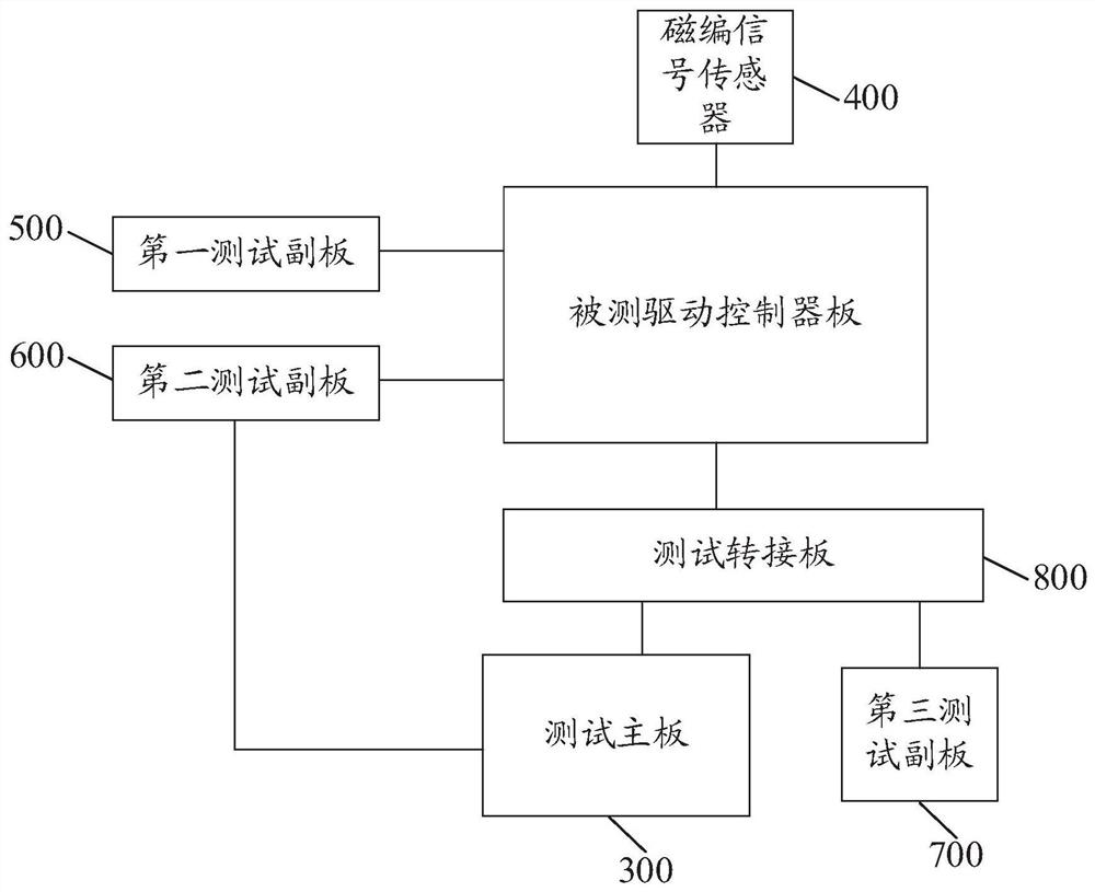
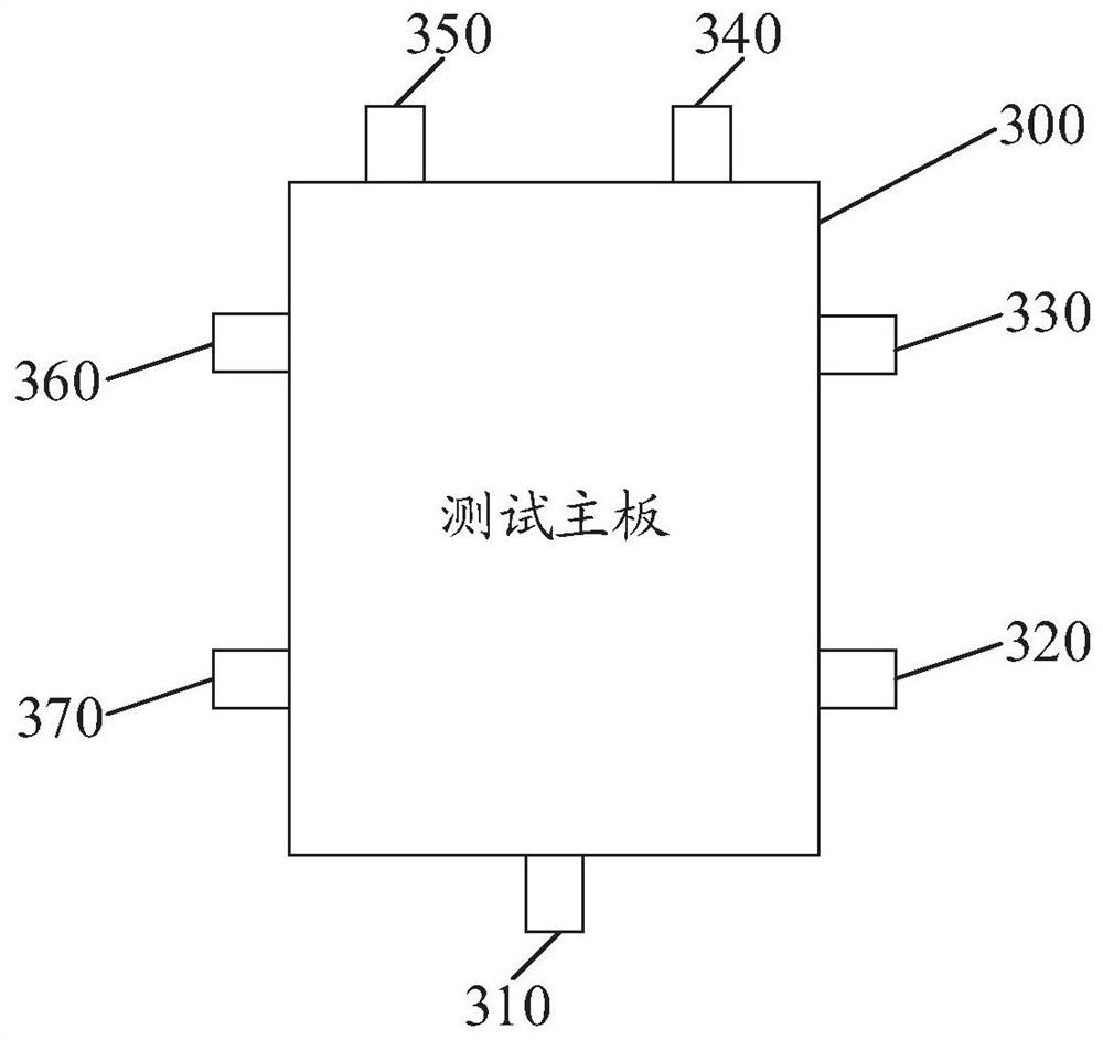
[0029] The present invention proposes a testing device for a collaborative manipulator to drive a controller board, such as Figure 1 to Figure 3 As shown, the test equipment includes an installation platform 100 and a test fixture 200, a test mainboard 300 and a power supply device arranged on the ...


PUM


Abstract

The invention discloses test equipment for a cooperative mechanical arm driving controller board. The test equipment comprises an installation platform, a test jig, a test mainboard and a power supplydevice, wherein the test jig, the test mainboard and the power supply device are disposed on the installation platform, and the test jig is provided with a fixed position. the test mainboard is provided with a first communication interface for outputting a detection result and a plurality of function interfaces which can be electrically connected with a tested driving controller board; and the power supply device can supply power to the test mainboard and the tested driving controller board. According to the test equipment, a test mode of the driving controller board is simplified, so that the detection efficiency is improved.

Description

technical field [0001] The invention relates to the technical field of driving devices, in particular to a testing device for a cooperative robot arm driving a controller board. Background technique [0002] The collaborative manipulator is generally composed of multiple joint modules. The joint module includes a motor, a reducer, a brake, a magnetic code disc, a magnetic encoder board, a joint servo drive controller board, and a joint servo drive power board. It has the characteristics of small size and high joint integration. [0003] The existing detection method for the drive controller board is generally to install the drive controller board on the joint module, and then check whether the joint module can operate normally. However, this detection method requires manual disassembly and assembly of the drive controller board repeatedly, resulting in low detection efficiency. Contents of the invention [0004] The main purpose of the present invention is to provide a t...

Claims


Application Information

Patent Timeline
Patent Type & Authority Applications(China)
IPC IPC(8): B25J19/00
CPCB25J19/0095
Inventor 黄海刚刘培超
Owner SHENZHEN YUEJIANG TECH CO LTD
Learn More