Oil and gas separation device and gas turbine engine

A separation device, oil and gas technology, applied in the directions of engine components, engine lubrication, separation methods, etc., can solve the problem of low oil and gas separation efficiency, and achieve the effects of easy oil and gas separation, prolonging residence time, and improving efficiency.

Active Publication Date: 2019-05-21
AECC COMML AIRCRAFT ENGINE CO LTD
View PDF4 Cites 0 Cited by
  • Summary
  • Abstract
  • Description
  • Claims
  • Application Information

AI Technical Summary

Problems solved by technology

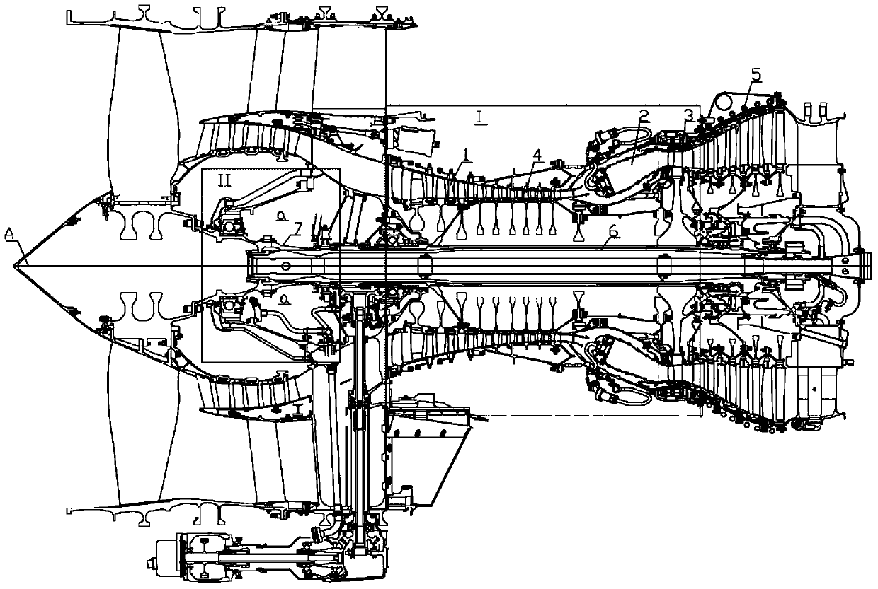
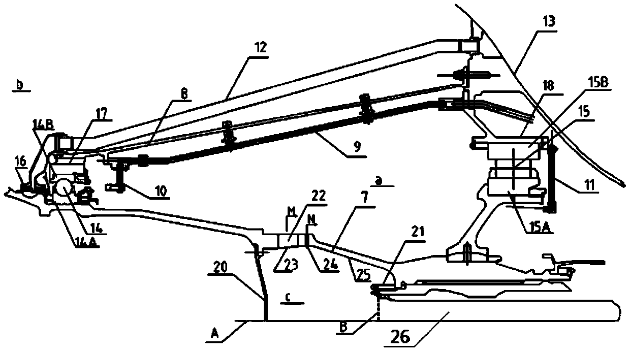
[0008] The purpose of the invention is to propose an oil-gas separation device and a gas turbine engine to solve the problem that the oil-gas separation efficiency of the oil-gas separation device in the prior art is not high

Method used


Image

  • Oil and gas separation device and gas turbine engine
  • Oil and gas separation device and gas turbine engine
  • Oil and gas separation device and gas turbine engine

Examples


Embodiment Construction

[0026] The technical solutions in the embodiments of the present invention will be clearly and completely described below in conjunction with the drawings in the embodiments of the present invention. Apparently, the described embodiments are only some of the embodiments of the present invention, not all of them. Based on the embodiments of the present invention, all other embodiments obtained by persons of ordinary skill in the art without making creative efforts fall within the protection scope of the present invention.

[0027] In describing the present invention, it should be understood that the terms "center", "transverse", "longitudinal", "front", "rear", "left", "right", "upper", "lower", " The orientations or positional relationships indicated by "vertical", "horizontal", "top", "bottom", "inner" and "outer" are based on the orientations or positional relationships shown in the drawings, and are only for the convenience of describing the present invention and Simplifie...


PUM


Abstract

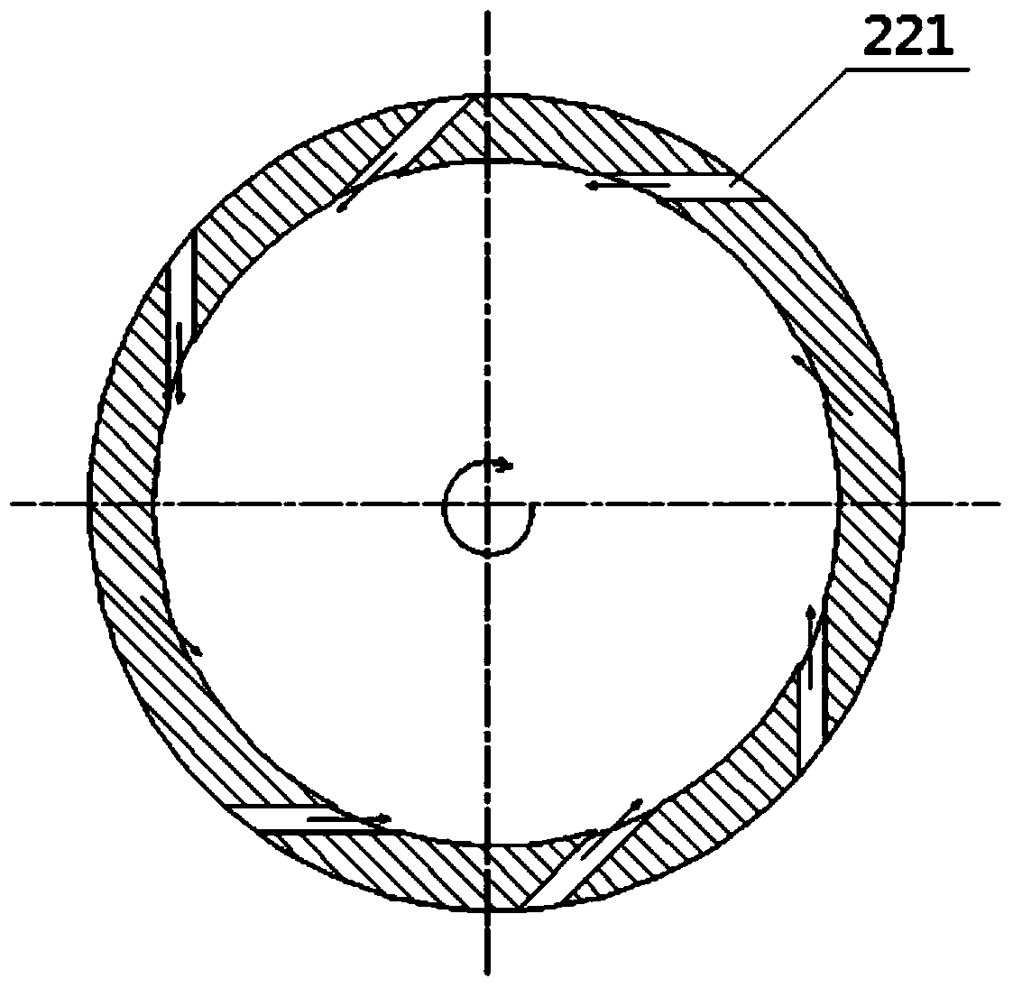
The invention relates to an oil-gas separation device and a gas turbine engine. The oil-gas separation device comprises a cavity structure provided with a separation cavity. The wall face of the separation cavity is provided with an inlet, a first outlet and a second outlet. The inlet comprises multiple tangential channels. The multiple tangential channels enable oil-gas mixture to enter the separation cavity in the tangential direction. The first outlet is arranged in the radial direction of the separation cavity, the second outlet is arranged in the axial direction of the separation cavity, the separation cavity is rotated to achieve oil-gas separation for the oil-gas mixture, oil obtained after separation flows out through the first outlet, and gas obtained through separation flows out through the second outlet. In the embodiment of the oil-gas separation device and the gas turbine engine, the oil-gas mixture entering the separation cavity has the large tangential speed and small or almost zero radial speed and axial speed, standing time of vortical motion of the oil-gas mixture in the separation cavity can be longer, and the oil-gas separation efficiency can be better improved.

Description

technical field [0001] The invention relates to the technical field of oil-gas separation, in particular to an oil-gas separation device and a gas turbine engine. Background technique [0002] A gas turbine engine generally mainly includes a compressor, a combustor and a high-pressure turbine. The compressor is mainly used to compress air and make it enter the core engine; the combustor is mainly used to mix compressed air and fuel, and complete combustion to generate High-energy gas flow; while the high-pressure turbine is mainly used to extract energy from the high-energy gas flow ejected from the combustion chamber to drive the compressor. In an aviation turbofan engine, the low-pressure turbine located downstream of the core engine extracts energy from the high-energy gas flow ejected from the combustion chamber and drives the fan, which provides the main thrust generated by the engine. [0003] The rotor is usually fixed by multiple fulcrum bearings in the engine. Gen...

Claims


Application Information

Patent Timeline
Patent Type & Authority Patents(China)
IPC IPC(8): F02C7/06C10G31/10B01D19/00
CPCB01D19/0036C10G31/10C10G2400/10F02C7/06
Inventor 曹渝华王军韩宁周欣欢
Owner AECC COMML AIRCRAFT ENGINE CO LTD
Why Eureka
Try Eureka