
Reverse-flow type frequency conversion speed regulation multi-fan array wind tunnel and test method thereof

A variable frequency speed regulation and multi-fan technology, applied in the field of fluid mechanics, can solve the problems of limited application fields and large energy loss, and achieve the effect of wide application fields and small energy loss

Pending Publication Date: 2017-12-05
STATE GRID FUJIAN ELECTRIC POWER CO LTD +3
View PDF7 Cites 13 Cited by
  • Summary
  • Abstract
  • Description
  • Claims
  • Application Information

AI Technical Summary

Problems solved by technology

[0003] The purpose of the present invention is to address the deficiencies of the prior art, to provide a backflow type variable frequency speed regulation multi-fan array wind tunnel and its test method, to solve the problems of large energy loss and limited application fields, and to provide a theory for scientific research and wind prevention and disaster reduction basis and guidance

Method used


Image

  • Reverse-flow type frequency conversion speed regulation multi-fan array wind tunnel and test method thereof
  • Reverse-flow type frequency conversion speed regulation multi-fan array wind tunnel and test method thereof
  • Reverse-flow type frequency conversion speed regulation multi-fan array wind tunnel and test method thereof

Examples


Embodiment 1

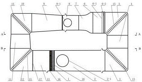
[0034]When the motor 14-5 in the multi-fan power section 1 is at a certain speed, the motor 14-5 is made to experience a process of "sudden acceleration-sudden deceleration" to drive the fan blade 14-9 to rotate in a "sharp acceleration-sudden deceleration", and the resulting The air flow is a pulsating air flow, at this time, the pulsating wind load test can be carried out in the first test section 2. The air flows through the first corner 3, the first recirculation section 4 and the second corner 5 and enters the stable section 6 without the damping net 6-1, and then enters the first diffusion section 9 through the contraction section 7 and the second test section 8. The kinetic energy in the diffusion section is converted into pressure energy, and the energy loss is reduced. The air flows through the third corner 10 and enters the second diffuser section 11 to convert kinetic energy into pressure energy again, further reducing energy loss. Finally, the air flows through th...

Embodiment 2

[0036] When the motor 14-5 in the multi-fan power section 1 is working stably at a certain speed, the fan blades 14-9 are driven to rotate at a corresponding speed, and the airflow generated passes through the first test section 2, the first corner 3, and the first return section 4. The second corner 5 enters the stable section 6. After passing through the honeycomb 6-2 and the two-layer damping net 6-1, the airflow becomes uniform and straight, and the pulsation decreases. After being accelerated by the contraction section 7, it enters the second test Section 8, at this time, the conventional wind load test can be carried out in the second test section 8. The airflow enters the first diffusion section 9 from the second test section 8, and the kinetic energy of the airflow is converted into pressure energy in the diffusion section, and the energy loss is reduced. The air flows through the third corner 10 and enters the second diffuser section 11 to convert kinetic energy into ...


PUM


Abstract

The invention relates to a reverse-flow type frequency conversion speed regulation multi-fan array wind tunnel and a test method thereof. The wind tunnel is a hollow-square structure integrally and comprises a multi-fan power section (1), a first test section (2), a first corner (3), a first reverse-flow section (4), a second corner (5), a stable section (6), a contraction section (7), a second test section (8), a first expansion section (9), a third corner (10), a second expansion section (11), a fourth corner (12) and a second reverse-flow section (13) which are sequentially connected. The adaptive control technology is employed to realize frequency conversion speed regulation of a multi-fan system, the first test section and the second test section are adjusted according to test objects; the reverse-flow type and double-test section modes are employed, and properties of small energy loss and wide application field are realized.

Description

technical field [0001] The invention relates to the technical field of fluid mechanics, in particular to a backflow type frequency conversion speed regulation multi-fan array wind tunnel and a test method thereof. Background technique [0002] With the development of science and technology, wind tunnel tests have been widely used in aerospace, construction, energy and other fields. At present, the more advanced wind field simulation technology is based on the active simulation technology of multi-fan array wind tunnel. The design idea of ​​multi-fan active control wind tunnel is derived from Teunissen’s multiple-jet wind tunnel (Multiple-jet wind tunnel), which consists of 8×8 jet tube arrays, each jet tube has an inner diameter of about 6.2mm, and the jet speed is controlled by valves , the test section is only 0.2m×0.2m×2.86m. Combined with the control of the ground roughness of the test section, Teunissen simulated the turbulent boundary layer flow field with a turbulen...

Claims


Application Information

Patent Timeline
IPC IPC(8): G01M9/04G01M9/02
CPCG01M9/02G01M9/04
Inventor 陈彬姚裕易弢李先影张明龙王健史志伟赵彪
Owner STATE GRID FUJIAN ELECTRIC POWER CO LTD
Learn More