Data transmission method and device, data receiving method and device, and electronic equipment

A data transmission method and user equipment technology, applied in digital transmission system, transmission path sub-channel allocation, transmission system, etc., can solve the problem that logical channels cannot transmit data, etc.

Active Publication Date: 2017-12-05
BEIJING XIAOMI MOBILE SOFTWARE CO LTD
View PDF3 Cites 39 Cited by
  • Summary
  • Abstract
  • Description
  • Claims
  • Application Information

AI Technical Summary

Problems solved by technology

[0004] One problem with this solution is that since the logical channel is bound to the carrier to which it is mapped, if the carrier bound to the logical channel is congested or has a link problem, the logical channel will not be able to transmit data

Method used


Image

  • Data transmission method and device, data receiving method and device, and electronic equipment
  • Data transmission method and device, data receiving method and device, and electronic equipment
  • Data transmission method and device, data receiving method and device, and electronic equipment

Examples


Embodiment Construction

[0128] The following will clearly and completely describe the technical solutions in the embodiments of the application with reference to the drawings in the embodiments of the application. Apparently, the described embodiments are only some of the embodiments of the application, not all of them. Based on the embodiments in this application, all other embodiments obtained by persons of ordinary skill in the art without making creative efforts belong to the scope of protection of this application.

[0129] Reference will now be made in detail to the exemplary embodiments, examples of which are illustrated in the accompanying drawings. When the following description refers to the accompanying drawings, the same numerals in different drawings refer to the same or similar elements unless otherwise indicated. The implementations described in the following exemplary examples do not represent all implementations consistent with the present disclosure. Rather, they are merely example...


PUM


Abstract

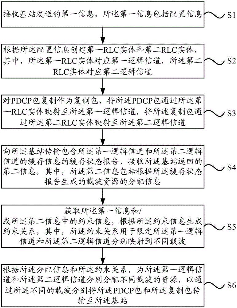
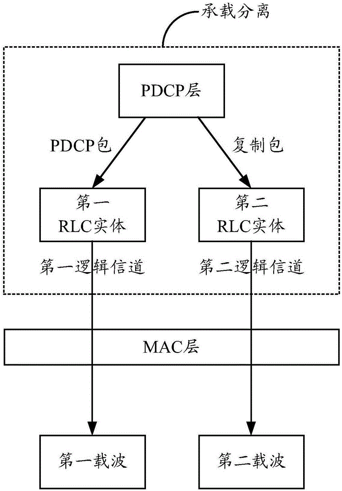
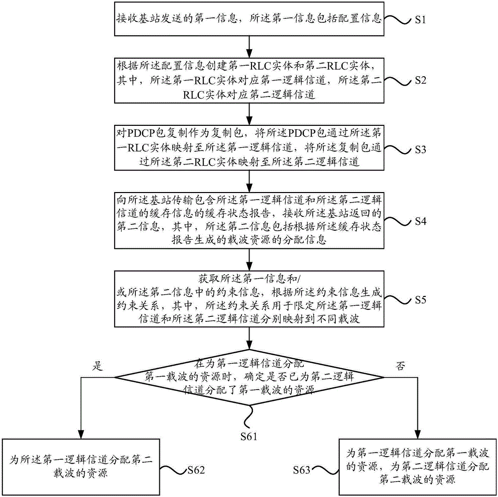
The invention relates to a data transmission method which comprises the following steps: receiving first information sent by a base station; creating a bearing separation; and the buffer status report comprising the buffer information of the first logical channel and the second logical channel is transmitted to the base station., receiving second information returned by the base station; acquiring first information and or the constraint information in the second information, and generating a constraint relation according to the constraint information, wherein, the constraint relation is used for limiting the first logical channel and the second logical channel to be mapped to different carriers respectively; and the resources of different carriers are respectively distributed for the first logical channel and the second logical channel according to the distribution information and the constraint relation. According to embodiments of the present disclosure, due to unbound logical channels and carriers for which resources are allocated, only the second logical channel allocation resources are defined for the first logical channel through different carriers., and therefore when it is detected that a certain carrier has congestion or a link and the like, logical channels mapped to the carriers can be adjusted to be mapped to other carriers.

Description

technical field [0001] The present disclosure relates to the field of communication technologies, and in particular, to a data transmission method, a data transmission device, a data receiving method, a data receiving device and electronic equipment. Background technique [0002] At present, in order to solve the reliability problem of data packet and signaling packet transmission, a scheme of duplicating data packets and signaling packets at the PDCP (packet data convergence protocol, data packet convergence protocol) layer on the user equipment side is mainly adopted. However, since the PDCP layer is located at the top layer of the protocol stack on the side of the wireless device, the replicated packet of the PDCP layer cannot be guaranteed to be sent through two carriers at the bottom layer, which may cause the signal quality on the same carrier to be poor, and the replicated If the packet is still sent on the carrier, the probability of its successful delivery will be v...

Claims


Application Information

Patent Timeline
Patent Type & Authority Applications(China)
IPC IPC(8): H04L5/00H04W36/02
CPCH04L5/006H04L5/0091H04W36/02
Inventor 江小威
Owner BEIJING XIAOMI MOBILE SOFTWARE CO LTD
Why Eureka
Try Eureka